


$)*""*%$
"$#1=4"$#-9A55545A
#$(%+$$
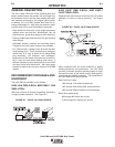
LN-9 GMA wire feeders are grounded to the power
source through the input cable. The power source
grounding cable must be properly connected to electri-
cal ground. See your power source operating manual
for details.
-%(!"%$$*%$
Connect a work lead of sufficient size and length
between the proper output terminal on the power
source and the work. See Table A-1. Be sure the con-
nection to the work makes tight metal-to-metal electri-
cal contact. Poor work lead connections can activate
the grounding lead protector and/or result in poor weld-
ing performance.
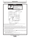
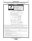
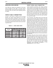
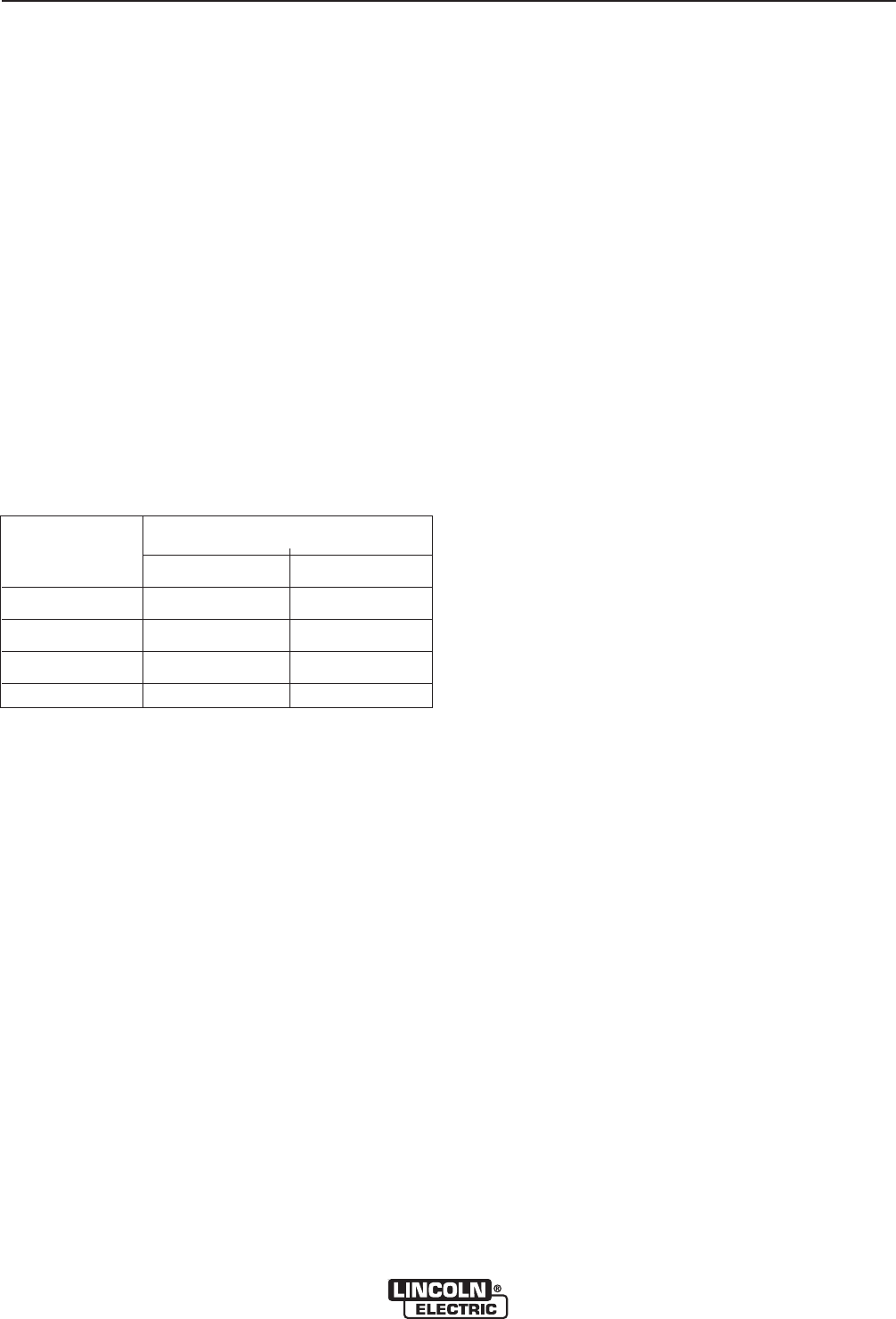
*"P-%(!")0)
DAA5=C
>??5A->A:12;5)9I5-
DCHH3;5
+?C>;5=7C8 5=7C8
<?B
<?B
<?B
<?B
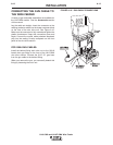
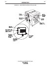
(*-%(!"%$$*%$
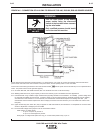
Lincoln specified procedures give voltage readings
taken between the work and the gun cable brass con-
nection block of the LN-9 GMA. To match these voltage
readings, the connection diagrams show the #21 lead
being extended and connected directly to the work
instead of #21 on the power source terminal strip (or
Dual Process Kit terminal strip). This extended lead
must be connected directly to the work. When using a
Dual Process Kit, you must extend the lead individual-
ly for each LN-9 GMA.
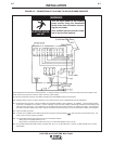
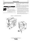
As an alternative, LN-9 GMA models are provided with
a quick-connect terminal splice connection in the #21
lead between the input Amphenol connector of the LN9
GMA and its polarity switch. See the LN-9 GMA wiring
diagram. This in-line connection consists of a red insu-
lated male and female .250 x .032 terminal pair locat-
ed in the lead harness. It runs along the right side of
the wire feed motor inside the control section of the LN-
9 GMA models and in the lead harness at the lower left
corner of the control box (near the input Amphenol) of
the LN-9F models. You may also open this #21 lead
and connect your own direct work lead equipped with a
.250 x .032 female quick-connect terminal to the male
side of the splice. This direct work lead connection
must be tape insulated, strain-relieved, and routed out-
side the LN-9 GMA control box to be connected direct-
ly to the work.
With either direct work lead connection method, the
LN-9 GMA regulates the power source to hold the arc
voltage constant, even with voltage drops in the elec-
trode lead, work lead, or work lead connection. If the
direct work lead becomes disconnected from the work,
the LN-9 GMA wire feeder will stop welding shortly
after the arc is struck. See the topic "Circuit
Protection and Automatic Shutdown" in the
Operation section of this manual.