


"%$*%"*%!
)&%%"#*(%("
!$$()"%"
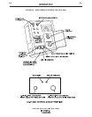
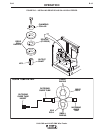
The Spindle should be located in the "%-(mounting hole.
(For 8" (200 mm) spools, a K468 spindle adapter must
first be slipped onto spindle.)
(For 13-14 lb. (6 Kg) Innershield coils, a K435 Coil
Adapter must be used).
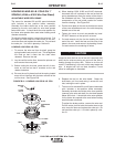
1) Depress the Release Bar on the Retaining Collar
and remove it from the spindle. $%* Eariler spin-
dles used a threaded collar.
2) Place the spool on the spindle making certain the
spindle brake pin enters one of the holes in the back
side of the spool. Be certain the wire comes off the
reel in a direction so as to de-reel from the bottom
of the coil.
3) Re-install the Retaining Collar. Make sure that the
Release Bar “pops up” and that the collar retainers
fully engage the retaining groove on the spindle.
"%$"!%"
+)$!%"("
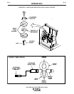
(For 50-60 lb Readi-Reels a K438 Readi Reel Adapter
must be used.)
The Spindle must be located in the +&&( mounting
hole.
1. With the K1504-1 Coil Reel mounted on to the 2"
(51 mm) spindle (or with reel laying flat on the floor)
loosen the spinner nut and remove the reel cover.
2. Before cutting the tie wires, place the coil of elec-
trode on the reel so it unwinds from the bottom as
the reel rotates.
3. Tighten the spinner nut against the reel cover much
as possible by hand using the reel cover spokes for
leverage. DO NOT hammer on the spinner nut
arms.
4. Cut and remove only the tie wire holding the free
end of the coil. Hook the free end around the rim of
the reel cover and secure it by wrapping it around.
Cut and remove the remaining tie wires.
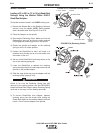
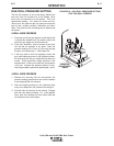
$"*(%$(! +)*#$*
1. Turn the Readi-Reel or spool until the free end of
the electrode is accessible.
2. While tightly holding the electrode, cut off the bent
end. Straighten the first six inches. Cut off the first
inch. (If the electrode is not properly straightened,
it may not feed or may not go into the outgoing
guide tube, causing a "birdnest.")
3. Insert the free end through the incoming guide
tube.
4. Press the gun trigger or "cold inch" (if used) and
push the electrode into the drive roll.
USE THE "COLD" TRIGGER SWITCH POSITION, OR
"COLD INCH" OPTION WHEN LOADING. WHEN
INCHING WITH A "HOT" GUN TRIGGER, THE ELEC-
TRODE AND DRIVE MECHANISM ARE ALWAYS
"HOT" TO WORK AND GROUND AND COULD
REMAIN "HOT" SEVERAL SECONDS AFTER THE
GUN TRIGGER IS RELEASED.
5. Inch the electrode through the gun.
6. Adjust the brake tension with the thumbscrew on
the spindle hub, until the reel turns freely but with
little or no overrun when wire feeding is stopped.
Do not overtighten.
%&(*%$
"$#1=4"$#-9A55545A
-($$