


#!$*)*-"$
+)*$"$#()&%$)
$)*(*$(*()*)
+)**&%-()%+(
>A
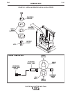
1. Connect electrode lead to terminal of desired
polarity.
2. Set toggle switch to same polarity as the electrode
cable connection.
3. Set toggle switch to "Output Control Remote."
4. Set mode switch to the desired position for the
process to be used.
,,
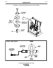
1. Connect electrode lead to terminal of desired
polarity.
2. Connect #21 control lead to the work polarity ter-
minal (+21 or -21), at the terminal strip, matching
the same polarity as the work cable connection.
3. Set toggle switch to "Output Control Remote."
()()()
1. Connect electrode lead to terminal of desired
polarity.
2. Set toggle switch to same polarity as the electrode
cable connection.
3. Set the toggle switch to "Remote."
4. Install voltage triangle to a position as close as
possible to desired arc voltage.
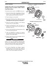
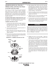
$%* Since the LN-9 GMA cannot control the
fixed OCV of R3S power sources, starting
difficulties may be experienced when strik-
ing the arc of processes which use a low
voltage or a narrow voltage range. The
following steps should remedy this difficul-
ty:
1 . The electrode stickout when starting should be
as close to procedural length as possible, and
the tip of the electrode should be clean and
held nearly touching the work.
2. Install the R3S voltage triangle to the position
higher than the desired arc voltage, provided it
does not result in out of range shutdown of the
LN-9 GMA while welding.
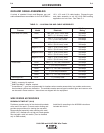
&+")&%-(&(%,
Refer to each machine Instruction Manual. The LN-9
GMA requires the K442-1 Pulse Power Filter Kit. (See
the Accessories section of this manual.)
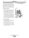
+)**"$#%$*(%")
1. Set the "Electrode Polarity" switch to same polarity
as the electrode lead.
2. Check that "Feed Direction" is set to forward.
3. Set the "Trigger Interlock" switch as desired.
4. Set the "Meter Reading" switch to "Wire Speed"
and adjust the "Wire Speed" rheostat so the meter
reads the desired wire feed speed.
5. Set the "Meter Reading" switch to "Volts" and
adjust the "Volts" rheostat so the meter reads the
desired arc voltage. IMPORTANT: Make certain
this setting is within the voltage output range of the
power source setting.
6. Load the LN-9 GMA with electrode.
%&(*%$
"$#1=4"$#-9A55545A