


(,(%""$)*""*%$
$$ (, (%"") %( (%""
-(()
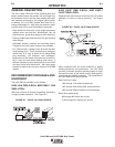
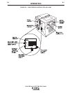
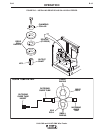
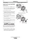
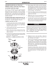
To change drive rolls on a 2-roll wire feeder, refer to
Figure B.5 and perform the following steps.
NOTE: Although an LN-9 GMA model is shown in
Figure B.5, the following procedure also
applies to LN-9F GMA models.
1. Rotate the latch knob on the quick release arm.
2. Remove the hex head screw and clamping collar.
Remove the drive roll from the shaft. On new
machines, remove the tape and the drive key.
3. The new roll to be installed is stamped for the size
to be fed. An "A" after the size indicates aluminum
wire. Remove the rolls from the kit and wipe them
clean. Wipe the output shaft and locating shoulder
clean.
4. Use the drive key, clamping collar, and hex head
screw to install the roll on the output shaft. Certain
size drive rolls consist of two roll halves, and may
contain a spacer. If the drive roll you are installing
contains a spacer, the spacer fits between the two
halves of the drive roll. Tighten the hex head
screw.
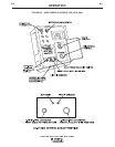
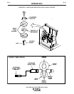
5. Back out the guide tube clamping screws. Remove
the old guide tubes, if installed.
6. Insert the outgoing guide tube (the one with the
plastic insert) into the front hole. If the guide tube
has a non-symmetrical chisel end, the larger radius
must face the drive roll. See Figure B.5. Push the
guide tube back as far as it will go and tighten the
clamping screw. Insert the incoming guide tube as
far back as it will go and tighten the clamping
screw. The clamping screws are dog points. When
the guide tubes are properly installed these dog
points will lock into the annular grooves in each of
the guide tubes.
7. Set the idle roll pressure as detailed in the Idle Roll
Pressure Setting procedure detailed later in this
section.
%&(*%$
"$#1=4"$#-9A55545A