


+$$"#$*$$
For instructions on periodic maintenance for the weld-
ing gun and cables, refer to the manual for your specif-
ic model of welding gun.
&(%&()&)$)%(#%+"
#%+$*$
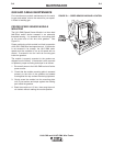
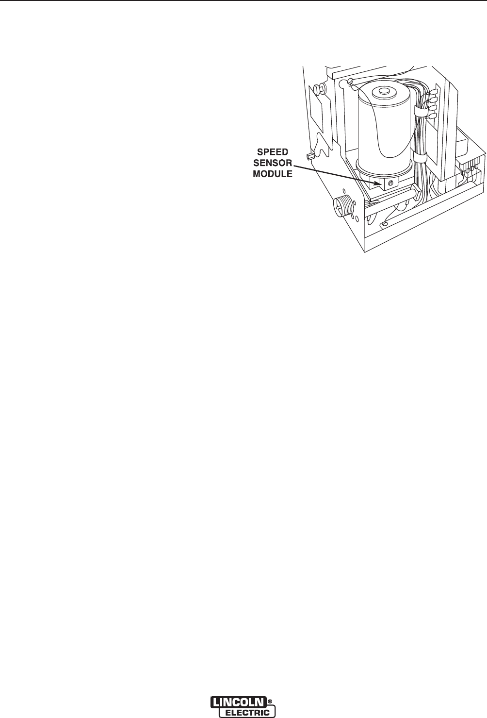
The LN-9 GMA Speed Sensor Module is a three lead
Hall-Effect switch device encased in an externally
threaded housing. It is screwed into a mounting plate
on the motor side of the wire drive gearbox. See
Figure D.1.
Proper positioning of this module is critical to operation
of the LN-9 GMA wire feed speed control. If the device
is not screwed in far enough, the LN-9 GMA motor
speed could be unstable or run at full speed with no
control. If screwed in too far it will rub a moving part
inside the gearbox.
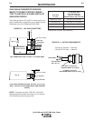
The module is properly mounted to the gearbox as
shipped from the factory. If the device is ever removed
or replaced, proper mounting technique is as follows:
1. Be sure all power to the LN-9 GMA is shut off at the
power source.
2. Check that the module mounting plate is screwed
securely to the side of the gearbox and seated
flush against the top surface after being tightened.
3. Gently screw the module into the mounting plate
until it just touches and stops against the rotating
part inside the gearbox.
4. Back the module out 1/2 turn, then snug the mod-
ule locknut without rotating the module position.
#$*$$
"$#1=4"$#-9A55545A
+(P)&)$)%(#%+""%*%$