


"%$$"%")%$R
)&$" !>A!-9A5(55;)C1=4
+)*"-(("(!
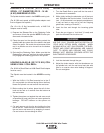
The mount for standard 50 and 60 pound electrode
coils includes a two position brake assembly.
Generally the brake should be a the inner position
(nearest to the wire reel shaft) for wire feed speeds
below 400 in/min. It should be at the outer position for
the faster wire speeds often used when feeding small
diameter electrode.
To adjust the brake position, remove the wire reel. Pull
the cotter pin that holds the brake shoe to the arm,
move the shoe and replace the cotter pin. Do not bend
the cotter pin - it is held in place by a friction fit.
"%$%("%"
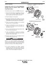
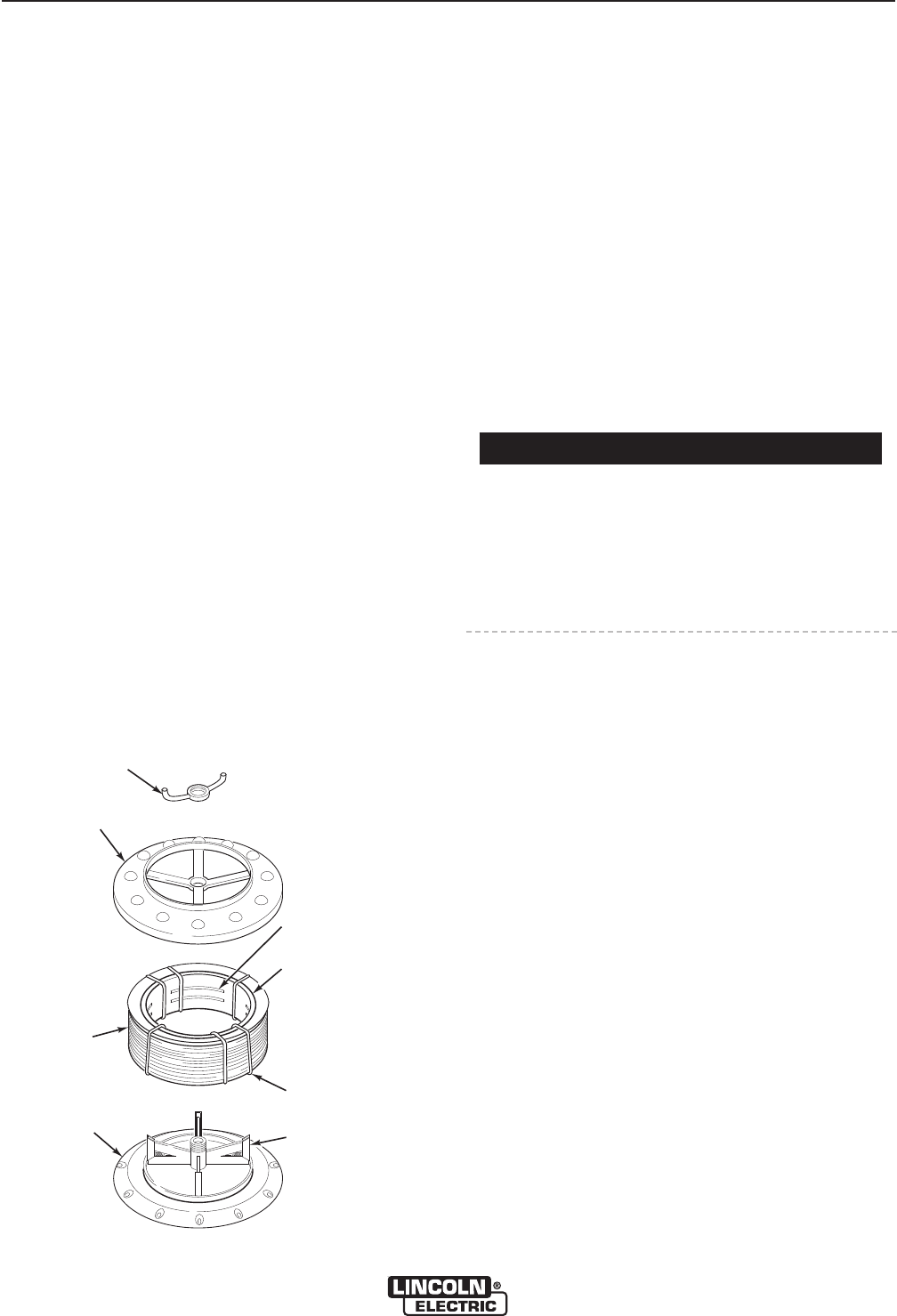
1. To remove the wire reel from its shaft, grasp the
spring loaded knob and pull it out. This straightens
the knob so that it seats into the shaft when
released. Remove the reel.
2. Lay the reel flat on the floor, loosen the spinner nut
and remove the cover plate.
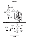
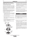
3. Before cutting the tie wires, place the coil of elec-
trode on the reel so that it unwinds as the reel
rotates clockwise.
a) Be sure the coil is placed so that the spring loaded
arms will not interfere with the later removal of the
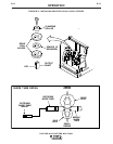
coil tie wires. See Figure B.8.
b) When loading 0.030, 0.035 and 0.045" electrode,
be certain the coil is placed on the reel so that the
spring loaded arms are at the center of the slots in
the cardboard coil liner. This provides the positive
compression of the coil sides needed for trouble
free wire feeding. See Figure B.8.
c) Put the cover plate on the reel so that the four arms
of the cover straddle and are in line with the spring
loaded arm of the reel.
4. Tighten the cover as much as possible by hand.
DO NOT hammer on the spinner nut arms.
5. Cut and remove only the tie wire holding the free
end of the coil. Insert the free end into one of the
holes in the cover and secure it by bending it back.
Cut and remove the remaining tie wires.
Always be sure the free end of the coil is securely held
while the tie wires are being cut and until the wire is
feeding through the drive rolls. Failure to do this will
result in "backlashing" of the coil, which may tangle the
wire. A tangled coil will not feed; therefore it must
either be untangled or discarded.
6. Replace the reel on the wire feeder. Grasp the
shaft knob, pull it out and swing it across the reel
hub, locking the reel in place.
7. The mount for standard 50 and 60 pound electrode
coils includes a two-position brake assembly.
Generally the brake should be at the inner position
(nearest to the wire reel shaft) for wire feed speeds
below 400 in/min. It should be at the outer position
for the faster wire speeds often used when feeding
small diameter electrode.
To adjust the brake position, remove the wire reel.
Pull the cotter pin that holds the brake shoe to the
arm, move the shoe and replace the cotter pin. Do
not bend the cotter pin - it is held in place by a fric-
tion fit.
%&(*%$
"$#1=4"$#-9A55545A
SPINNER
NUT
COVER
PLATE
COIL
REEL
SLOTS
CARDBOARD
COIL
LINER
TIE WIRE
SPRING
LOADED
ARM
SPINNER
NUT
COVER
PLATE
COIL
REEL
SLOTS
CARDBOARD
COIL
LINER
TIE WIRE
SPRING
LOADED
ARM
+(P"%$%("%"
+*%$