


+."(/'+&#$*%$**)
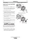
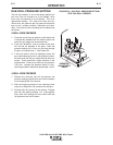
The power for 115 volt AC auxiliary equipment can be
obtained from the terminals inside the LN-9 GMA con-
trol box. The contacts are “hot” whenever the trigger is
pressed or the unit is welding. The current draw of this
circuit must not exceed 1/4 ampere.
*+($ * $&+* &%-( *% * &%-(
)%+( % * * )%$$* )-*
%(&(%(#$*%""%-$-%(!
"$##%"
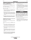
Install 1/4” quick connect terminals to the leads from
the auxiliary equipment. Route the leads to the termi-
nals marked #32A and #7 which come through the rec-
tangular hole in the control section sheet metal near
the wire feed motor.
"$#(%""$(%""#%")
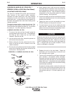
Install terminals for #6 screws to the leads from the
auxiliary equipment. Route the leads to the terminals
#32A and #7 on the terminal strip on the inside bottom
of the control box.
$%*)
1. The K418 and K419 burnback timer does not delay
the opening of the auxiliary equipment contacts. If
you want to continue power to auxiliary equipment
during the burnback time, this can be accom-
plished only if you are using an R3S, DC-400 or
DC-600 power source. Connect the 115 volt AC
auxiliary equipment leads to #4 and #31 on the
power source terminal strip. The auxiliary equip-
ment power requirements should not exceed 15
watts.
This alternate connection cannot be used with the
DC-250 or CV-400, 500-I Power Sources.
2. If the LN-9 GMA gas solenoid valve is not required,
the gas solenoid terminals (#32A and #7A) may be
used in conjunction with the K418 GMA Timer Kit to
obtain pre-weld and/or post-weld timing functions
for 115V AC auxiliary equipment. However, the
gas solenoid must be disconnected and the auxil-
iary equipment current draw must not exceed 1/4
ampere.
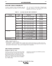
%&*%$"'+&#$*$
))%()
&%-($&+*"))#")
!!!
Required to connect wire feeder to power source.
Includes multiconductor control cable and the proper
size electrode cable for the welding current to be used.
Specify length and maximum welding current.
• K196 Input Cable Assemblies - For power sources
with terminal strip wire feeder connections and stud
output terminals.
• K595 Input Cable Assemblies - For power sources
with MS-type (Amphenol) wire feeder receptacle and
stud output terminals.
• K596 Input Cable Assemblies - For power sources
with MS-type (Amphenol) wire feeder receptacle and
Twist-Mate™ output connectors.
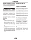
-((")*$)$#%+$*$)
"-(("#%+$*$)*$!
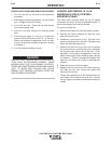
The assembly includes a framework to which is
attached the 50-60 lb. wire reel, a mounting spindle, a
dust shield, a lift bail, and a cable clamp for fastening
the input cable assembly. It is easily mounted to the
basic wire feed unit by three bolts. The reel mounting
spindle is the pull knob type with a built-in brake.
The brake pad is adjustable for proper braking at low
or high wire feed speeds.
"(("
M
#%+$*$)*$
!
The assembly includes a framework to which is
attached a 2" O.D. spindle with adjustable brake and
50-60 lb. Readi-Reel Adapter. Includes a lift bail and
cable clamp for fastening the input cable assembly,
and easily mounts to the LN-9 GMA feeder. Does not
include dust shield.
Can also be used for up to 60 lb. spools with 2" I.D.
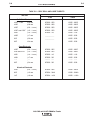
))%()
"$#1=4"$#-9A55545A
-($$