


RANGER® 10,000 & RANGER® 10,000 PLUS
INSTALLATION
A-7 A-7
LOCATION / VENTILATION
The welder should be located to provide an unrestrict-
ed flow of clean, cool air to the cooling air inlets and to
avoid heated air coming out of the welder recirculating
back to the cooling air inlet. Also, locate the welder so
that engine exhaust fumes are properly vented to an
outside area.
STACKING
RANGER® 10,000 machines cannot be stacked.
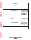
CONNECTION OF LINCOLN ELECTRIC
WIRE FEEDERS
Shut off welder before making any electrical
connections.
------------------------------------------------------------------------
WIRE FEED (CONSTANT VOLTAGE)
CONNECTION OF LN-15 ACROSS-THE-ARC WIRE
FEEDER
The LN-15 has an internal contactor and the electrode
is not energized until the gun trigger is closed. When
the gun trigger is closed the wire will begin to feed and
the welding process is started.
a. Shut the welder off.
b.
Connect the electrode cable from the LN-15 to
the
“ELECTRODE” terminal of the welder. Connect
the work cable to the “TO WORK” terminal of the
welder.
c. Set the Polarity switch to the desired polarity, either
DC (-) or DC (+).
d. Attach the single lead from the front of the LN-15
to work using the spring clip at the end of the lead.
This is a control lead to supply current to the wire
feeder motor; it does not carry welding current.
e. Set the “RANGE” switch to the “WIRE FEED-CV”
position
f. Place the Engine switch in the “High Idle” position.
g. Adjust the wire feed speed at the LN-15 and adjust
the welding voltage with the output “CONTROL” at
the welder.
Output “CONTROL” must be set above 3.
Note: LN-15 Control Cable model will not work with
the RANGER® 10,000.
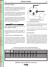
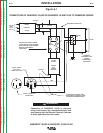
CONNECTION OF THE LN-25
a. Shut the welder off.
b.
Connect the electrode cable from the LN-25 to
the
“ELECTRODE” terminal of the welder. Connect
the work cable to the “TO WORK” terminal of the
welder.
c. Position the welder “Polarity” switch to the desired
polarity, either DC (-) or DC (+).
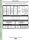
RANGER® 10,000 and RANGER® 10,000 PLUS
Constant Current 225 Amps AC @ 25 Volts
210 Amps DC @ 25 Volts
Constant Voltage 200 Amps DC @ 20 Volts
d. Position the “RANGE” switch to the “WIRE FEED”
position.
e. Attach the single lead from the LN-25 control box
to the work using the spring clip on the end of the
lead - it carries no welding current.
f. Place the engine switch in the “AUTO” position.
g. Adjust wire feed speed at the LN-25 and adjust the
welding voltage with the output “CONTROL” at the
welder.
NOTE: The welding electrode is energized at all times,
unless an LN-25 with built-in contactor is used.
If the output “CONTROL” is set below “3”, the
LN-25 contactor may not pull in.
CONNECTION OF K930-2 TIG MODULE TO THE
RANGER® 10,000 OR RANGER® 10,000 PLUS.
The TIG Module is an accessory that provides high
frequency and shielding gas control for AC and DC
GTAW (TIG) welding. See IM528 supplied with the
TIG Module for installation instructions.
NOTE: The TIG Module does not require the use of a
high frequency bypass capacitor. However, if
any other high frequency equipment is used, a
Bypass Capacitor Kit (T12246) must be
installed in the RANGER® 10,000.
.
INSTRUCTIONS
ADDITIONAL SAFETY PRECAUTIONS
Always operate the welder with the roof and case sides
in place as this provides maximum protection from
moving parts and assures proper cooling air flow.
Read and understand all Safety Precautions before
operating this machine. Always follow these and any
other safety procedures included in this manual and in
the Engine Ownerʼs Manual.
WELDER OPERATION
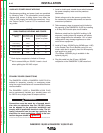
WELDER OUTPUT
• Maximum Open Circuit Voltage at 3700 RPM is
80 Volts RMS.
• Duty Cycle is the percentage of time the load is
being applied in a 10 minute period. For example, a
60% duty cycle represents 6 minutes of load and 4
minutes of no load in a 10 minute period. Duty Cycle
for the RANGER® 10,000 is 100%.
WARNING
Return to Section TOC Return to Section TOC Return to Section TOC Return to Section TOC
Return to Master TOC Return to Master TOC Return to Master TOC Return to Master TOC