


RANGER® 10,000 & RANGER® 10,000 PLUS
TROUBLESHOOTING & REPAIR
F-49 F-49
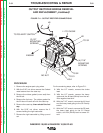
Be sure to follow the recommended static-
free methods for handling printed circuit
boards. Failure to do so can result in perma-
nent damage to the equipment.
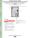
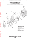
12. With the 1/4” phillips head screw driver,
remove four self tapping screws holding
the printed circuit board.
13. Replace the old printed circuit board with
a new one.
14. Connect the 12-pin molex plug.
15. Connect the 4-pin molex plug.
16. Connect two 1/4” Q.C. wires to P.C.
Board.
17. Replace any cable ties that were cut dur-
ing the removal procedure.
18. Replace 4 self tapping screws previously
removed.
19. Reinstall the case side, fuel cap, lift bail
gasket, case top, and spark plug wires.
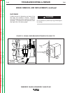
PRINTED CIRCUIT BOARD REMOVAL
AND REPLACEMENT
(continued)
CAUTION
Return to Section TOC Return to Section TOC Return to Section TOC Return to Section TOC
Return to Master TOC Return to Master TOC Return to Master TOC Return to Master TOC