


RANGER® 10,000 & RANGER® 10,000 PLUS
THEORY OF OPERATION
E-5 E-5
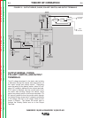
OUTPUT BRIDGE, CHOKE,
POLARITY SWITCH, AND OUTPUT
TERMINALS
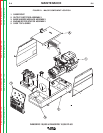
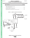
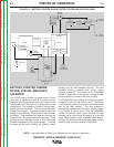
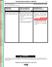
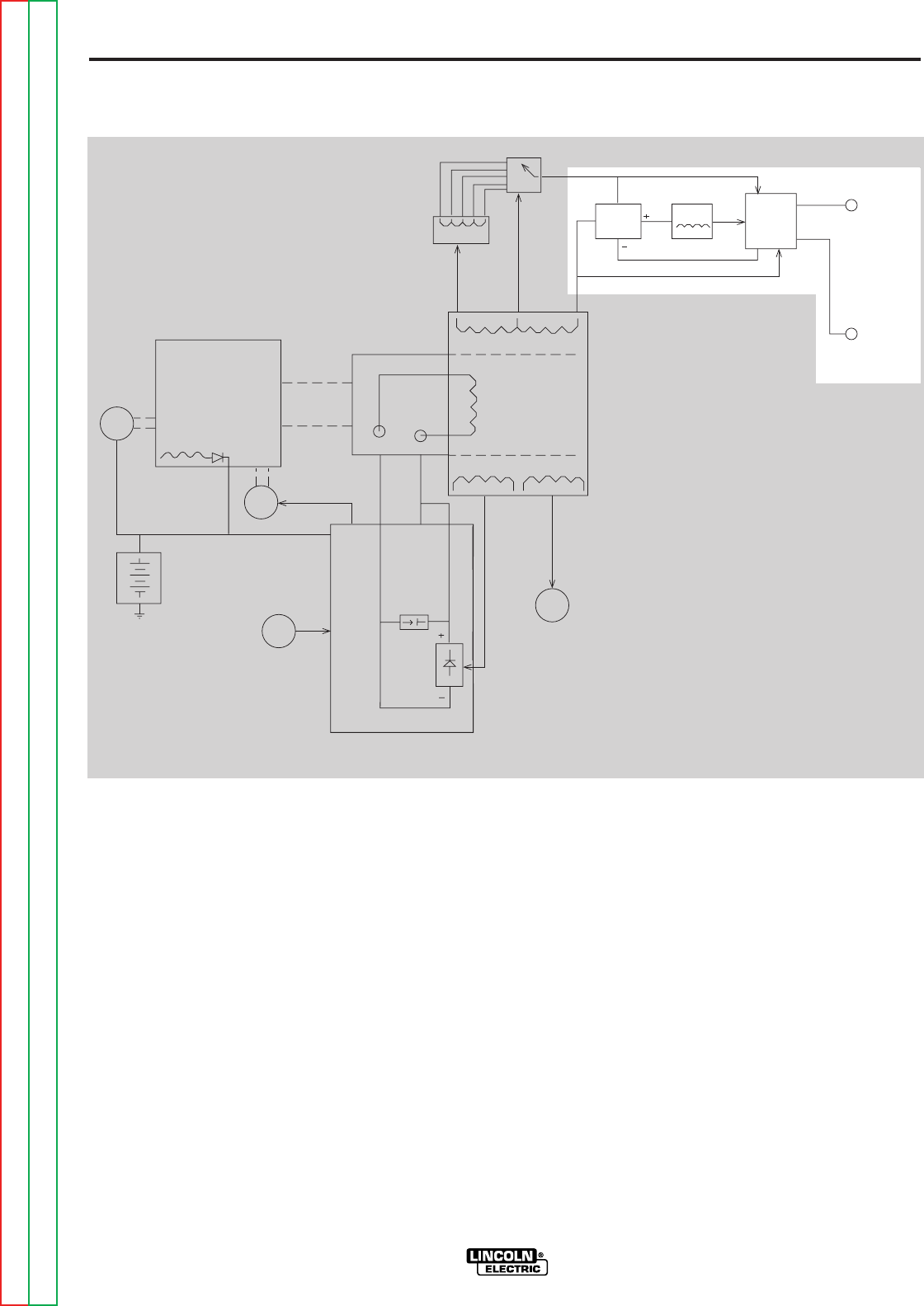
The AC voltage developed in the stator weld winding
is delivered, through the reactor and range switch, to
the output bridge and polarity switch. Depending
upon the setting of the polarity switch, either AC volt-
age or DC voltage is delivered to the output terminals.
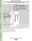
If AC output is selected, then the current path is from
the stator weld winding through the reactor, range
switch and polarity switch to the output terminals. If a
DC output is called for then the current path is through
the Output Bridge, where the AC voltage is rectified to
a DC voltage, and then to the choke, where the DC
output is filtered. The filtered DC current path is
through the Polarity Switch and on to the Output
Terminals.
STARTER ENGINE
BATTERY
IDLER
SOLENOID
OUTPUT
CONTROL
MECHANICAL
ROTATION
FIELD
CAPACITOR
R
OTOR
SLIP
RINGS
115 & 230VAC
RECEPTACLES
ROTOR
STATOR
STATOR
REACTOR
RANGE
SWITCH
OUTPUT
BRIDGE
C
HOKE
AC
A
C
POLARITY
SWITCH
ELECTRODE
TERMINAL
WORK
T
ERMINAL
FLYWHEEL
A
LTERNATOR
CV
TAP
PRINTED CIRCUIT
BOARD
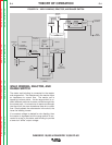
FIGURE E.5 – OUTPUT BRIDGE, CHOKE, POLARITY SWITCH, AND OUTPUT TERMINALS
Return to Section TOC Return to Section TOC Return to Section TOC Return to Section TOC
Return to Master TOC Return to Master TOC Return to Master TOC Return to Master TOC