


RANGER® 10,000 & RANGER® 10,000 PLUS
Section F-1 Section F-1
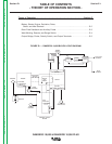
TABLE OF CONTENTS
- TROUBLESHOOTING & REPAIR SECTION -
Troubleshooting & Repair Section........................................................................Section F
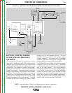
How to Use Troubleshooting Guide..............................................................................F-2
PC Board Troubleshooting Procedures ........................................................................F-3
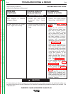
Troubleshooting Guide ........................................................................................F4 - F-13
Test Procedures
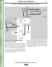
Rotor Voltage Test ................................................................................................F-15
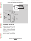
Rotor Resistance Test ..........................................................................................F-17
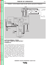
Auxiliary and Field Winding Test...........................................................................F-21
Output Rectifier Bridge Test .................................................................................F-25
Charging Circuit Test ............................................................................................F-27
Engine Throttle Adjustment Test ..........................................................................F-29
Oscilloscope Waveforms ............................................................................................F-33
Normal Open Circuit Voltage Waveform (115 VAC Supply) .................................F-33
Typical DC Weld Output Waveform (CV Mode) – Machine Loaded.....................F-34
Typical DC Weld Output Waveform (CC Mode) – Machine Loaded ....................F-35
Typical AC Weld Output Waveform – Machine Loaded .......................................F-36
Abnormal Open Circuit Weld Voltage Waveform (CV Mode, one diode open)....F-37
Abnormal Open Circuit DC Weld Voltage Waveform ...........................................F-38
Normal Open Circuit Weld Voltage Waveform (CV Mode) ...................................F-39
Normal Open Circuit DC Weld Voltage Waveform ...............................................F-40
Normal Open Circuit AC Weld Voltage Waveform ...............................................F-41
Replacement Procedures............................................................................................F-43
Brush Removal and Replacement........................................................................F-43
Printed Circuit Board Removal and Replacement ...............................................F-47
Output Rectifier Bridge Removal and Replacement............................................F-51
Engine Rotor Removal and Replacement (Kit S20788) .......................................F-55
Retest After Repair......................................................................................................F-60
Return to Master TOC Return to Master TOC Return to Master TOC Return to Master TOC