


RANGER® 10,000 & RANGER® 10,000 PLUS
THEORY OF OPERATION
E-3 E-3
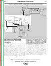
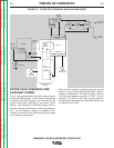
ROTOR FIELD FEEDBACK AND
AUXILIARY POWER
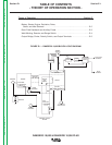
The AC voltage developed in the field winding is fed to
the full wave field bridge. The DC output of the bridge
is filtered by the field capacitor and controlled by the
printed circuit board according to the output control
setting. This filtered and controlled voltage is fed to
the rotor winding via the brush and slip ring configura-
tion. As the feedback voltage is increased or de-
creased, the outputs of the weld and auxiliary windings
are increased or decreased.
When full field voltage is applied to the rotor and the
engine is running at high speed (3700 RPM), a 230 AC
voltage is developed in the stator auxiliary winding.
This winding is tapped to provide 115 VAC. The two
voltages, (115 VAC and 230 VAC), are connected to
the appropriate receptacles and offer 9000 watts (total)
of continuous AC power.
FIGURE E.3 – ROTOR FIELD FEEDBACK AND AUXILIARY POWER
STARTER ENGINE
BATTERY
I
DLER
S
OLENOID
OUTPUT
CONTROL
MECHANICAL
ROTATION
FIELD
CAPACITOR
ROTOR
SLIP
R
INGS
115 & 230VAC
RECEPTACLES
ROTOR
STATOR
S
TAT O R
R
EACTOR
RANGE
SWITCH
OUTPUT
BRIDGE
CHOKE
AC
AC
POLARITY
SWITCH
ELECTRODE
TERMINAL
WORK
TERMINAL
FLYWHEEL
ALTERNATOR
CV
TAP
PRINTED CIRCUIT
BOARD
Return to Section TOC Return to Section TOC Return to Section TOC Return to Section TOC
Return to Master TOC Return to Master TOC Return to Master TOC Return to Master TOC