


TROUBLESHOOTING & REPAIR
F-56 F-56
POWER WAVE 455M/MSTT
Return to Section TOC Return to Section TOC Return to Section TOC Return to Section TOC
Return to Master TOC Return to Master TOC Return to Master TOC Return to Master TOC
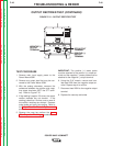
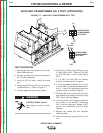
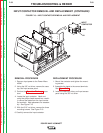
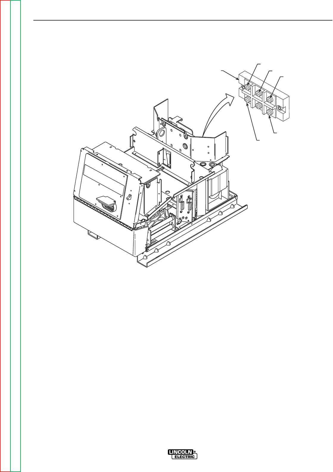
NEG (-)
POS (+)
A
B
C
INPUT
RECTIFIER
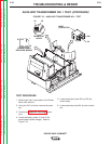
FIGURE F.18 – INPUT RECTIFIER REMOVAL AND REPLACEMENT
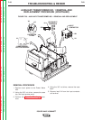
INPUT RECTIFIER REMOVAL AND REPLACEMENT (CONTINUED)
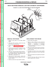
REMOVAL PROCEDURE
1. Remove input power to the Power Wave
455M.
2. Using the 3/8” nut driver, remove the case
top, and input access panel.
3. Perform the Capacitor Discharge proce-
dure.
4. Locate and remove the RTV sealant from the
input rectifier connection terminals. See
Figure F. 18.
5. Label and, using the phillips head screwdriv-
er, carefully remove the five leads from the
input rectifier terminals. Note placement for
reassembly. See Figure F.18.
6. Using the 3/16” allen wrench, remove the
two mounting screws and washers from the
rectifier module.
7. Carefully remove the input rectifier module.
REPLACEMENT PROCEDURE
1. Clean heat sink surfaces.
2. Apply an even coating of joint compound
(Penetrox A-13) to both the heat sink and
module mounting surfaces.
The joint compound should be 0.002 - 0.005
in. thick per surface.
3. Mount the module to the heat sink and even-
ly torque the mounting screws (with wash-
ers) to 44 in/lbs.
4. Assemble the leads to the correct module
terminals and torque to 26 in/lbs. See Figure
F.18.
5. Apply RTV sealant to the rectifier connection
terminals.
6. Install the case top, sides, and input access
panel using the 3/8” nut driver.