


ELECTRICAL DIAGRAMS
G-7 G-7
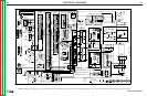
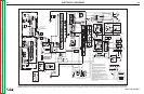
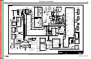
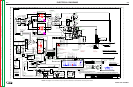
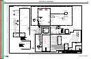
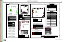
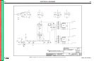
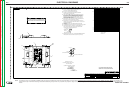
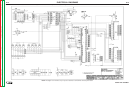
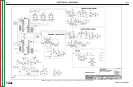
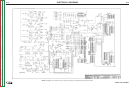
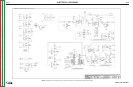
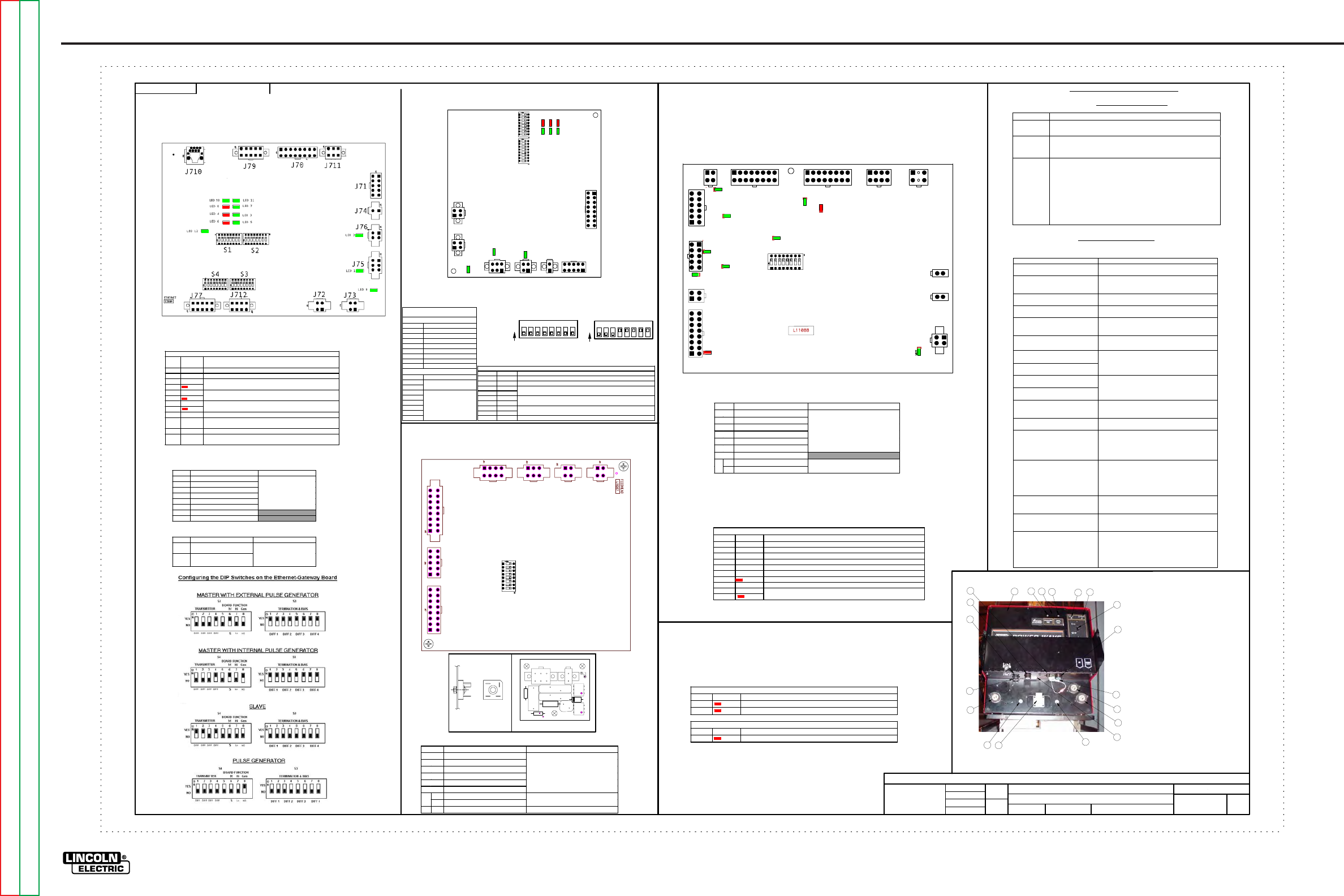
SCHEMATIC - ENTIRE MACHINE - CODES 10957 - 11311 PG 3 OF 3 (G4421)
NOTE: This diagram is for reference only. It may not be accurate for all machines covered by this manual.
POWER WAVE 455M/MSTT
Return to Section TOC Return to Section TOC Return to Section TOC Return to Section TOC
Return to Master TOC Return to Master TOC Return to Master TOC Return to Master TOC
EN-170
S
O
L
ID
E
D
G
E
G4421
ENGINEERING CONTROLLED
MANUFACTURER:
No
CONTROL BOARD, CHANGED 2J4 TO 3J4
G4421
INVERTER WELDERS
455M MACHINE SCHEMATIC
NONE
G4050
F.Valencic
S.Poole
.
DRAWN BY:
DESIGN INFORMATION
ENGINEER:
APPROVED:
REFERENCE:
EQUIPMENT TYPE:
SUBJECT:
SCALE:
2/1/2007
MATERIAL
DISPOSITION:
APPROVAL
DATE:
PROJECT
NUMBER:
UF
CRM22115-GC
PAGE ___ OF ___
3
DOCUMENT
NUMBER:
DOCUMENT
REVISION:
THIS DOCUMENT CONTAINS PROPRIETARY INFORMATION OWNED BY LINCOLN GLOBAL, INC. AND MAY NOT BE DUPLICATED, COMMUNICATED
TO OTHER PARTIES OR USED FOR ANY PURPOSE WITHOUT THE EXPRESS WRITTEN PERMISSION OF LINCOLN GLOBAL, INC.
PROPRIETARY & CONFIDENTIAL:
F
THE INFORMATION ON THIS
PRINT IS FOR REFERENCE
ONLY. COMPONENTS AND
CIRCUITRY MAY BE
DIFFERENT
FROM AN ACTUAL MACHINE.
CHANGE DETAIL:
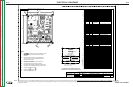
1. Power Switch
2. Status Light
3. High Temperature Light
4. 10 Amp Wire Feeder Circuit Breaker
5. Auxiliary Power Circuit Breaker
6. Work Sense Lead Connector
7. Arclink Receptacle
8. DeviceNET Connector (not shown)*
9. I/O Connector*
10. RS232 Connector
11. Work Stud
12. STT Stud
13. Electrode Stud
14. Robotic Interface Connector*
15. Auxiliary Output (110V or 220V)
16. Ethernet Connector*
17. Wire Drive Interface Module (not shown)*
18. Wire Drive Status LED*
19. Communication Interface Module (not shown)*
20. Communication Status LED*
* Not Standard in Base Model
ETHERNET MODULE
CONTROL BOARD
3
Description of LED functions on the Power Wave 455M
For reference only
L11088 Digital Control PC Board
LED # COLOR
FUNCTION
1 Green Indicates +15VDC from power supply board is present
2 Green Indicates –15VDC from power supply board is present
3 Green Indicates +5VDC for +5SPI from power supply board is present
4 Green Indicates +15VDC for +15SPI from power supply board is present
5 Green Indicates +5VDC for +5V from power supply board is present
6 Green Indicates +5VDC for +5VRS232 from power supply board is present
7 Red FAULT Signal (See software group for coding)
8 Green Indicates +5VDC for +5CAN from power supply board is present
9 Green
10 Red
ArcLink Status Indicators (Main System Master ArcLink Connection) Solid
Green only when functional (See software for error codes)
Description of LED functions on the Power Wave 455M
For reference only
G3632 Digital Power Supply Board
LED # COLOR FUNCTION
1 Red Indicates +5VDC SPI supply is present
2 Red Indicates +5VDC control supply is present
L11078 +40 Volt DC Bus Board
LED # COLOR FUNCTION
1 Red Indicates +40 VDC supply is present
Control Board DIP Switch:
stnemmoCnoitpircseDhctiwS
1
Object Instance LSB
2
Object Instance MSB
3
Equipment Group 1 Select
4
Equipment Group 2 Select
5
Equipment Group 3 Select
6
Equipment Group 4 Select
Used for Arclink configuration
7
Reserved for future use
off
work sense lead not connected
8
on
work sense lead connected
Used for configuring work sense lead
Feed Head Board DIP Switch:
stnemmoCnoitpircseDhctiwS
1 Object Instance LSB
2 Object Instance MSB
3 Equipment Group 1 Select
4 Equipment Group 2 Select
5 Equipment Group 3 Select
6 Equipment Group 4 Select
Used for Arclink Configuration
off Electrode polarity positive (default)
7
on Electrode polarity negative
Used for configuring electrode polarity
8
off Low speed gear (default) Used for confi
g
urin
g
wirefeeder
gear ratio
Ethernet Board DIP Switch :
Bank S1
Switch Description Comments
1 Object Instance LSB
2 Object Instance MSB
3 Equipment Group 1 Select
4 Equipment Group 2 Select
5 Equipment Group 3 Select
6 Equipment Group 4 Select
Used for Arclink
Configuration
7 Reserved for future use
8 Reserved for future use
Table 15
Bank S2
Switch Description Comments
1 - 2 Devicenet Baud Rate
3 - 4
Devicenet Mac ID
Used for DeviceNet
configuration
J75
J76
J74
J71
J73
J72
J70
GATEWAY
L11046
DEVICENET MODULE
J72
J73
J75
J76
J74
J71
J70
(OPTIONAL K2206)
S1
S2
LED6
LED4
LED8
LED5
LED3
LED7
LED2
LED1
LED9
Case Front Detail
1
2
3
18
17
20
8
7
6
16
11
4
15
5
12
13
10
9
14
Power Wave 455M/STT CE
(shown with Wire Drive Interface Module
& Ethernet communication Module)
Description of LED functions on the Power Wave 455M
For reference only
G3894 Ethernet Gateway PC Board
LED
#
COLOR FUNCTION
1 Green Indicates Isolated Module Section Supply is ON
2 Green Indicates DeviceNet Supply is ON
3 Green
4 Red
ArcLink Status Indicators (Main System
Slave
ArcLink Connection)
Solid Green only when functional (See software for error codes)
5 Green
6 Red
Reserved For Future Use
7 Green
8 Red
DeviceNet Status Indicators (See software group for coding)
9 Green Indicates Isolated ArcLink Section Supply is ON
10 Green 10Base-T Link Status ON indicates functional ethernet link has been
established
11 Green Receiver Polarity ON indicates proper ethernet signal polarity
12 Green Indicates I/O+5V Supply is ON This is used by differential I/O pair 4
circuitry, J712 pins 1 and 2.
Voltage Sense Board
M19540
J1
99/08/04@11:34:37
J2
99/08/04@11:28:10
VOLTAGE SENSE SELECT
R1
R
3
OCI1 OCI2
R2
C1
D1
L1
TP1
TP2
WIRE DRIVE MODULE
(OPTIONAL K2205)
S1
J87
J86
J85
J84
J83
J82 J81
NO P.C. BOARD MOUNTED LED's
Diode Detail
LED 9
LED 10
LED 5
LED 1
LED 2
LED 3
LED 4
LED6
LED7
LED 8
S1
J11
J10A
J10B
POWER BOARDS
(OPTIONAL K2207)
Description of LED functions on Power-Wave type systems
L11046 DeviceNet Gateway PC Board
LED # COLOR FUNCTION
1 Green Indicates Isolated Module Section Supply is ON
2 Green Indicates DeviceNet Supply is ON
3 Green
4 Red
ArcLink Status Indicators (Main System Slave ArcLink Connection) Solid
Green only when functional (See software for error codes)
5 Green
6 Red
Module Status Indicators (See software group)
7 Green
8 Red
DeviceNet Status Indicators (See software group for coding)
9 Green Indicates Isolated ArcLink Section Supply is ON
19
1
2 3
4
5 6
7
8
O
N
1
2 3
4
5 6
7
8
O
N
'Bank S2 Default'
'Bank S1 Default'
Con
f
iguring the DIP swi
t
ches
on the Devicenet Board
Switch Description
1 Object Instance LSB (see Table 1)
2 Object Instance MSB (see Table 1)
3 Equipment Group 1 Select
4 Equipment Group 2 Select
5 Equipment Group 3 Select
6 Equipment Group 4 Select
7 Reserved for future use
8 Reserved for future use
Switch Description
1
2
3
4
5 DeviceNet Mac ID
6 Default ID=62
7
8
Bank (S1)
Devicenet Board DIP Switch
Bank (S1)
DeviceNet Baud Rate
J5
J6
J7
J8
J9
J4
J3
J2
J1
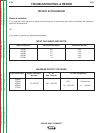
Troubleshooting the PowerWave
Using the Status LED
GNINAEM
Steady Green
System OK. Power source communicating normally with wire feeder and its
components.
Blinking Green
Occurs during a reset, and indicates the Power Wave is mapping (identifying)
each component in the system. Normal for first 1-10 seconds after power is
turned on, or if the system configuration is changed during operation
Alternating
Green and Red
Non-recoverable system fault. If the PS Status light is flashing any combination
of red and green, errors are present in the Power Wave. Read the error code
before the machine is turned off.
Error Code interpretation through the Status light is detailed in the Service
Manual. Individual code digits are flashed in red with a long pause between
digits. If more than one code is present, the codes will be separated by a green
light.
To clear the error, turn power source off, and back on to reset.
Error codes for the PowerWave
The following is a list of possible error codes that the Power Wave can output via the status light
noitacidnI # edoC rorrE
11 CAN communication bus off.
Probably due to excessive number of communication
errors.
12 User Interface time out error.
UI is no longer responding to the Power Source. The
most likely cause is a fault/bad connection in the
communication leads or control cable.
21 Unprogrammed Weld Mode.
Contact the Service Department for instructions on
reloading the Welding Software.
22 Empty Weld Table.
Contact the Service Department for instructions on
reloading the Welding Software.
23 Weld Table checksum error.
Contact the Service Department for instructions on
reloading the Welding Software.
31 Primary overcurrent error.
Excessive Primary current present. May be related to a
switch board or output rectifier failure.
32 Capacitor “A” under voltage
(Left side facing machine)
33 Capacitor “B” under voltage
(Right side facing machine)
Low voltage on the main capacitors. May be caused by
improper input configuration, or an open/short circuit
in the primary side of the machine.
34 Capacitor “A” over voltage
(Left side facing machine)
35 Capacitor “B” over voltage
(Right side facing machine)
Excess voltage on the main capacitors. May be caused
by improper input configuration, or an open/short
circuit in the primary side of the machine.
36 Thermal error
Indicates over temperature. Usually accompanied by
Thermal LED. Check fan operation. Be sure process
does not exceed duty cycle limit of the machine.
37 Softstart error
Capacitor precharge failed. Usually accompanied by
codes 32-35.
41 Secondary overcurrent error
The secondary (weld) current limit has been exceeded.
When this occurs the machine output will phase back
to 100 amps, typically resulting in a condition refered
to as “noodle welding”
42 Ground lead Current Shutdown
(On K2202-4 machines only)
The K2202-4 has a special circuit installed that
monitors current flowing on the input ground lead.
When current is sensed, the machine will turn the
welding output off. The machine will need to be turned
off for several seconds and then back on to clear this
error.
43 Capacitor delta error
The maximum voltage difference between the main
capacitors has been exceeded. May be accompanied by
errors 32-35.
49 Single phase error
Indicates machine is running on single phase input
power. Usually caused by the loss of the middle leg
(L2).
Other
Error codes that contain three or four digits are defined
as fatal errors. These codes generally indicate internal
errors on the PS Control Board. If cycling the input
power on the machine does not clear the error, try
reloading the operating system. If this fails, replace the
control board.