


TROUBLESHOOTING & REPAIR
F-64 F-64
POWER WAVE 455M/MSTT
Return to Section TOC Return to Section TOC Return to Section TOC Return to Section TOC
Return to Master TOC Return to Master TOC Return to Master TOC Return to Master TOC
INPUT
CONTACTOR
601
X4
CB4 CIRCUIT
BREAKER &
115V RECEPTACLE
LEADS 33/32
P50
P52
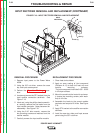
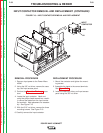
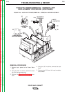
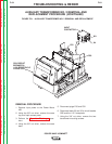
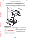
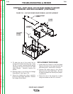
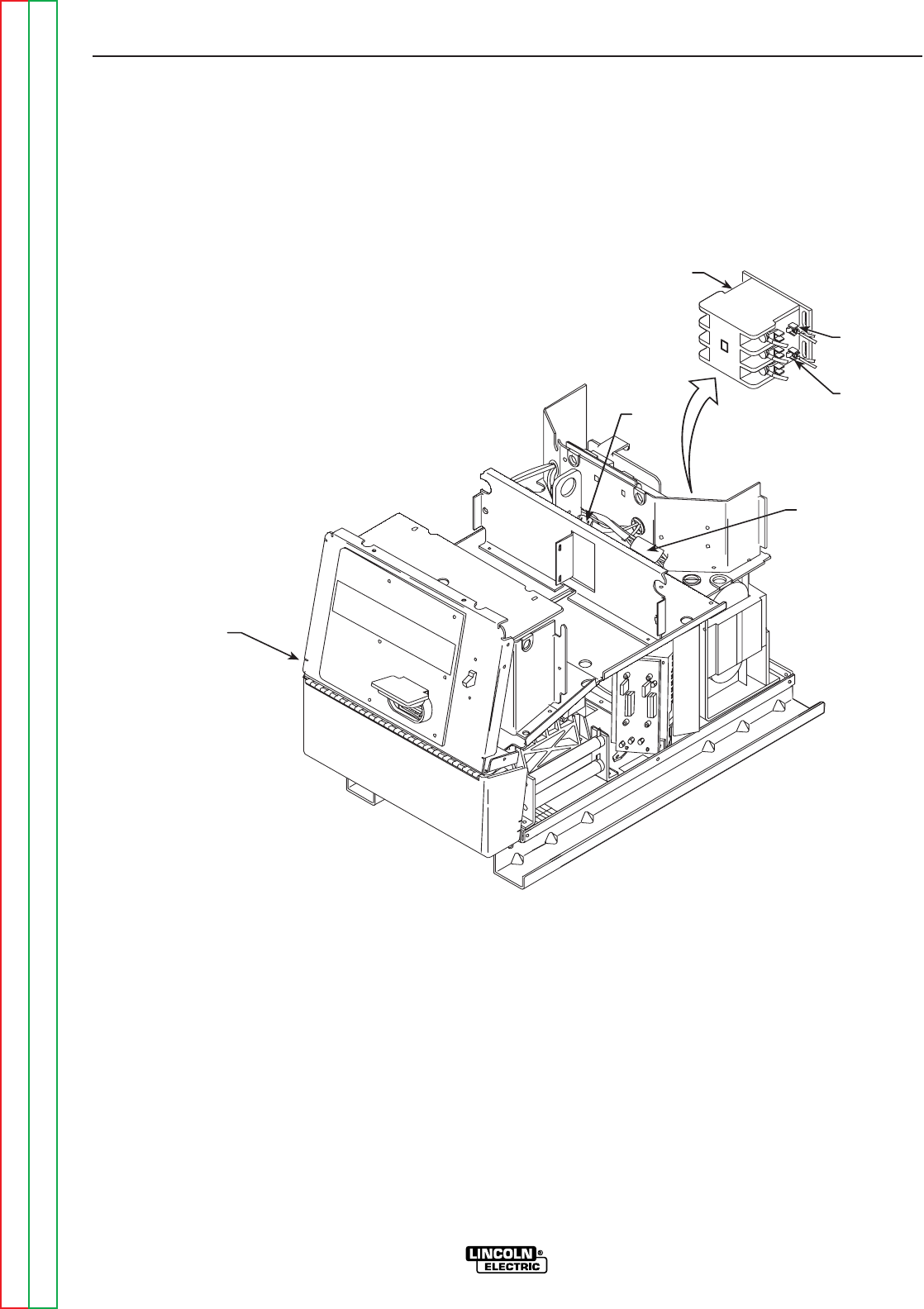
FIGURE F.21 – AUXILIARY TRANSFORMER NO. 2 REMOVAL AND REPLACEMENT
AUXILIARY TRANSFORMER NO. 2 REMOVAL AND
REPLACEMENT PROCEDURE (CONTINUED)
REMOVAL PROCEDURE
1. Remove input power to the Power Wave
455.
2. Using the 3/8” nut driver, remove the case
top, and input access panel.
3. Perform the Capacitor Discharge proce-
dure.
4. Using the 3/8” nut driver, remove the case
back.
5. Disconnect plugs P50 and P52.
6. Disconnect leads 33 and 32 to circuit breaker
CB2 and the 115 V receptacle.
7. Using the 3/8” nut driver, remove the two
transformer mounting screws.