


TROUBLESHOOTING & REPAIR
F-13 F-13
POWER WAVE 455M/MSTT
Return to Section TOC Return to Section TOC Return to Section TOC Return to Section TOC
Return to Master TOC Return to Master TOC Return to Master TOC Return to Master TOC
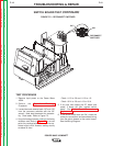
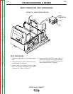
SWITCH
BOARD
11/12
OR
15/16
13/14
OR
17/18
-20 +19
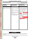
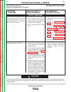
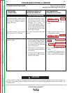
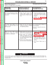
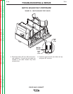
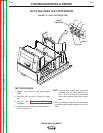
FIGURE F.3 – SWITCH BOARD TEST POINTS
SWITCH BOARD TEST (CONTINUED)
8. Reconnect leads 19C and 19D to the recon-
nect switches. Ensure that the leads are
installed in the same location they were
removed from.
9. Install the right and left case sides and top
using the 3/8” nut driver.