


TROUBLESHOOTING & REPAIR
F-74 F-74
POWER WAVE 455M/MSTT
Return to Section TOC Return to Section TOC Return to Section TOC Return to Section TOC
Return to Master TOC Return to Master TOC Return to Master TOC Return to Master TOC
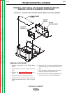
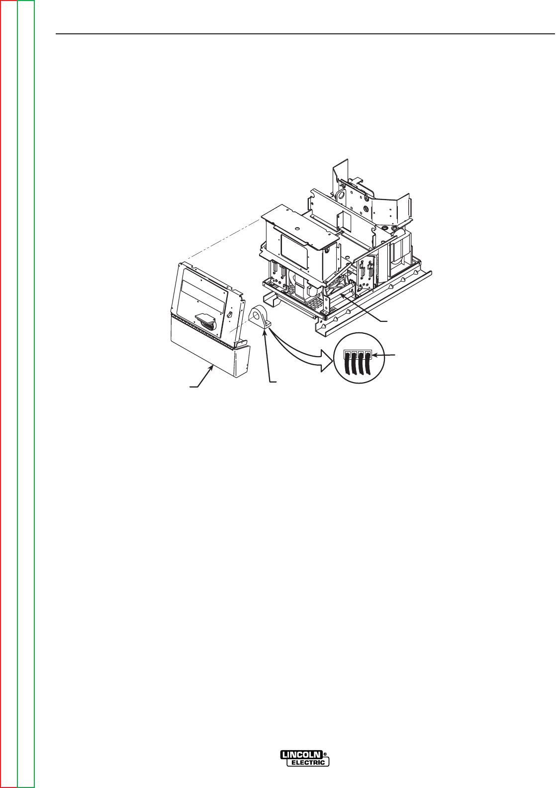
CURRENT
TRANSDUCER
P90
1234
RESISTOR
ASSEMBLY
STT OUTPUT
TERMINAL
(TOP RIGHT)
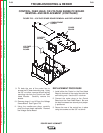
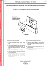
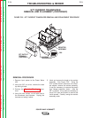
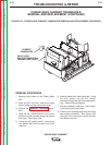
FIGURE F.25 – STT CURRENT TRANSDUCER REMOVAL AND REPLACEMENT PROCEDURE
STT CURRENT TRANSDUCER
REMOVAL AND PLACEMENT (CONTINUED)
REMOVAL PROCEDURE
1. Remove input power to the Power Wave
455.
2. Using the 3/8” nut driver, remove the case
top and right side.
3. Perform the Capacitor Discharge proce-
dure.
4. Using the wire cutters, cut all cable ties to
the transducer lead harness. Unplug the
harness and swing it aside.
5. Label and remove the leads to the resistor
assembly. See Figure F.25. Using the
5/16” socket wrench, extension and univer-
sal adapter, remove the resistor assembly.
It may be necessary to remove the plastic
high voltage protection shield. (Use the
3/8” nut driver.) It may also be necessary to
use a 5/16” open end wrench to remove the
inside screws. Carefully swing the resistor
assembly aside.