


Observe Safety Guidelines TROUBLESHOOTING GUIDE
detailed in the beginning of this manual.
CAUTION
If for any reason you do not understand the test procedures or are unable to perform the test/repairs safely, con-
tact the Lincoln Electric Service Department for electrical troubleshooting assistance before you proceed. Call
1-888-935-3877.
PROBLEMS
(SYMPTOMS)
POSSIBLE AREAS OF
MISADJUSTMENT(S)
RECOMMENDED
COURSE OF ACTION
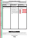
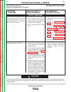
OUTPUT PROBLEMS
The Power Wave 455M does not
have welding output. The main
input contactor CR1 is not activat-
ing. Fan may be running.
1. Turn the input power off and
make certain the reconnect
panel is configured correctly for
the applied input voltage.
2. If the Thermal light is lit, See
next.
1. Check status led on case front
evaluate
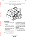
2. Perform the Input Contactor
Test.
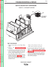
3. Perform the Input Board Test.
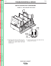
4. Perform the T1 Auxiliary
Transformer Test.
5. Perform the Input Rectifier
Test.
6. Perform the Switch Board
Test.
7. Perform the Power Board Test.
8. The Control Board may be faulty.
F-6 F-6
TROUBLESHOOTING & REPAIR
POWER WAVE 455M/MSTT
Return to Section TOC Return to Section TOC Return to Section TOC Return to Section TOC
Return to Master TOC Return to Master TOC Return to Master TOC Return to Master TOC
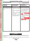
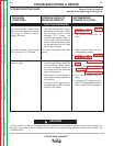
The thermal light is lit. The
machine regularly "overheats."
1. The welding application may be
exceeding the recommended
duty cycle and/or current limits
of the machine.
2. Dirt and dust may have clogged
the cooling channels inside the
machine. Refer to the Maint-
enance Section of this manual.
3. Air intake and exhaust louvers
may be blocked due to inade-
quate clearance around the
machine.
4. Make sure the fan is functioning
correctly. Machines above code
10500 are equipped with F.A.N.
(fan as needed) circuitry. The
fan runs whenever the output is
enabled, whether under load or
open circuit conditions. The fan
also runs for a period of time
(approximately 5 minutes) after
the output is disabled.
1. One of the thermostats may be
faulty. Also check associated
wiring for loose or faulty con-
nections. See the Wiring
Diagram.