


TROUBLESHOOTING & REPAIR
F-33 F-33
POWER WAVE 455M/MSTT
Return to Section TOC Return to Section TOC Return to Section TOC Return to Section TOC
Return to Master TOC Return to Master TOC Return to Master TOC Return to Master TOC
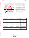
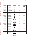
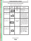
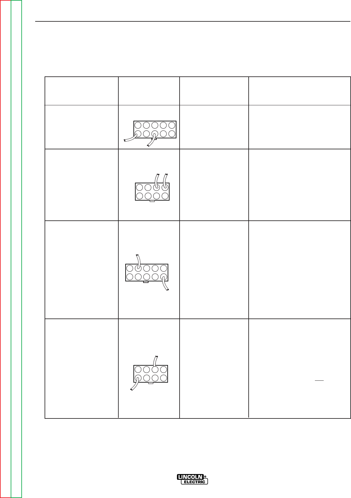
TABLE F.4 – INPUT BOARD VOLTAGE CHECKS
INPUT BOARD FUNCTION TEST(CONTINUED)
TEST POINTS
PLUG J61 PIN 8 (H1D)
TO
PLUG J61 PIN 6 (612)
PLUG J60 PIN 3 (238)
TO
PLUG J60 PIN 4 (604)
PLUG J61 PIN 10 (T3)
TO
PLUG J61 PIN 2 (T1)
PLUG J60 PIN 3 (238)
TO
PLUG J60 PIN 5 (232)
LEAD
NUMBERS
J61
J60
J61
J60
EXPECTED
VOLTAGE
READINGS
SAME AS
INPUT
VOLTAGE
13 – 15 VDC
A LITTLE LESS
THAN INPUT
VOLTAGE
13 – 15 VDC
COMMENTS
Present when Input
Switch SW1 is closed.
If not, check input lines and line
switch and wiring.
This is the Coil Voltage for the
Pre-Charge Relay. Normally this
DC Voltage will be present 6 sec-
onds after Input Switch SW1 is
activated. This 13 - 15 VDC will
remain for approximately 6 sec-
onds and then be removed. The
Relay is controlled by the Control
Board. See the Wiring Diagram.
This is Pre-Charge Voltage and
will normally be present 6 sec-
onds after activating Input Switch
SW1. The Pre-Charge Voltage
should remain for approximately 6
seconds and then be removed. It
should start at zero and ramp up
to 170 - 200 V.A.C. If zero volts -
check input board resistors, and
check for a shorted main input
rectifier.
This is the DC Coil Voltage for the
Control Relay. Normally this DC
Voltage will be present approxi-
mately 12 seconds after Input
Switch SW1 is activated. The
Relay is controlled by the Control
PC Board. See the Wiring
Diagram. Voltage will not
be
applied if capacitor precharge is
incorrect.
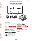
#612
H1D
T1
T3
#238
#604
#238
#232