


P 3/10
Repair
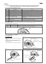
1) Assemble Spacer and Safety cover to Bearing box.
(Fig. 3 on page 2)
2) Assemble Safety cover to Bearing box.
(Fig. 3 on page 2)
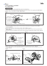
Link Safety cover to Blade case with Tension spring 4
as illustrated in Fig. 4.
Note: Be sure to follow the instructions in Fig. 4.
Otherwise, pivoting action of Safety cover
will be interfered by Tension spring 4.
3) Secure Safety cover to Bearing box with Retaining
ring S-42. Fasten Rubber sleeve 6 to Blade case with
Pan head screw M6x20. (Figs. 1, 2 on page 2)
[3] DISASSEMBLY/ASSEMBLY
[3] -1. Safety Cover (cont.)
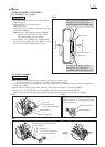
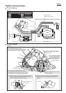
ASSEMBLING
Blade side
Tension spring 4
Bearing box side
Fig. 4
Blade case
Safety cover
Pass the hook of Tension spring 4
through the hole on Safety cover
from Bearing box side to Blade side.
Pass the hook of Tension spring 4
through the hole on Blade case
from Blade side to Bearing box side.
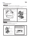
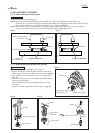
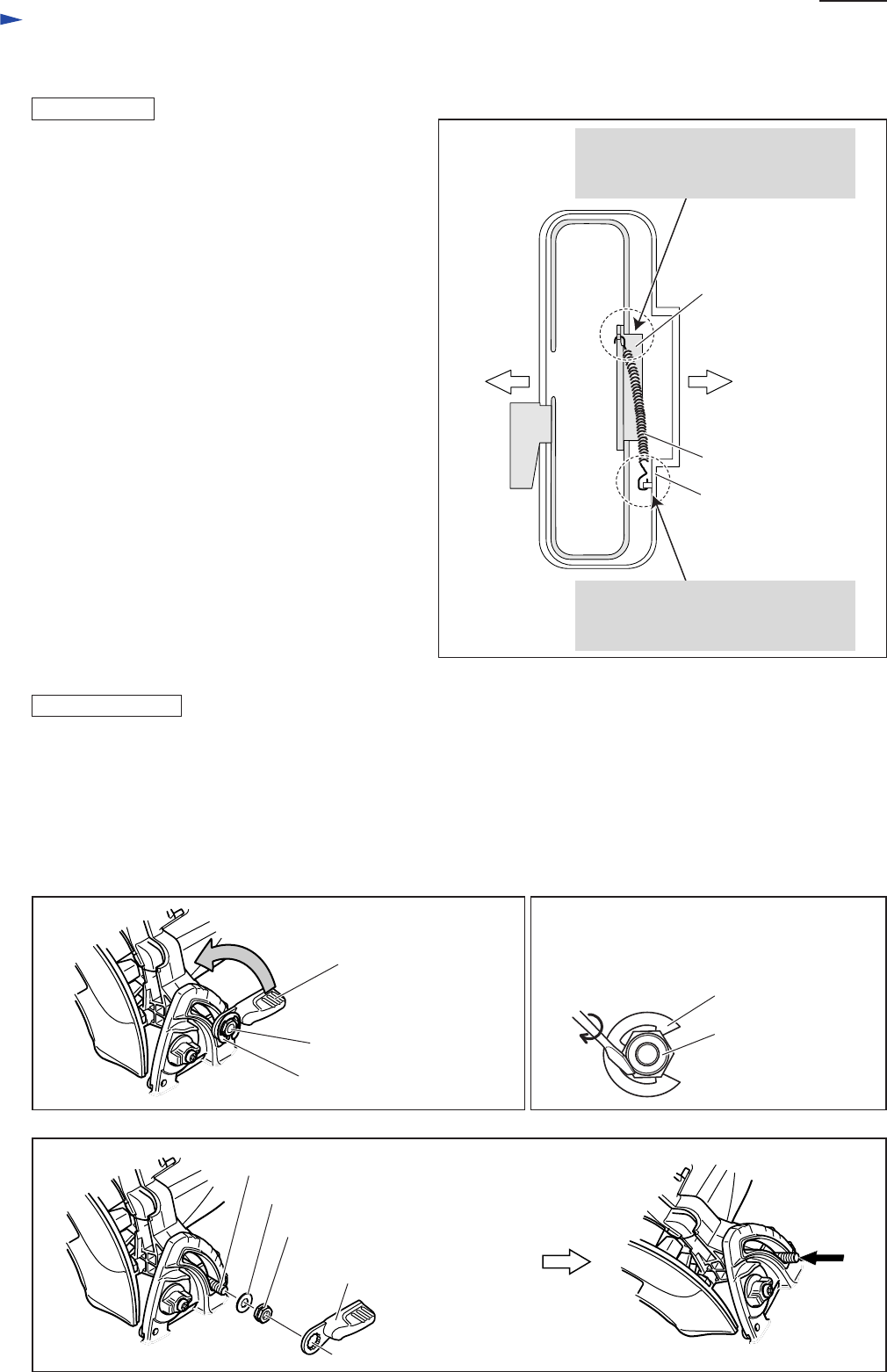
[3] -2. Base Complete
Fig. 6
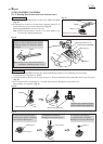
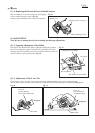
Fig. 7
Fig. 5
Lever 56
(the one used for
bevel angle adjustment)
Hex nut M8-13
Bow stop ring E-12
Flat-head square-neck bolt M8x24
Flat washer 8
Hex nut M8-13
Note: The above illustrations show the conditions after removal of Safety cover.
It is not necessary to remove Safety cover when replacing Base complete.
1) Loosen Hex nut M8-13 by turning Lever 56 (the one used for bevel angle adjustment) in the direction of the arrow
as illustrated in Fig. 5.
2) Remove Bow stop ring E-12 from Hex nut M8-13 using slotted screwdriver as described in Fig. 6.
3) Remove Lever 56, Hex nut M8-13 and Flat washer 8 from Flat-head square-neck bolt M8x24.
Then remove Flat-head square-neck bolt M8x24 by pushing it in the direction of the black arrow. (Fig. 7)
Remove Bow stop ring E-12 from the groove
of Hex nut M8-13 by twisting the ring using
slotted screwdriver.
Hex nut M8-13
Bow stop ring E-12
DISASSEMBLING
Lever 56 (the one used for
bevel angle adjustment)