


P 7/10
Repair
[3] DISASSEMBLY/ASSEMBLY
[3] -5. Bearing Box Section and Gear Section (cont.)
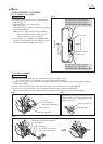
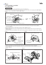
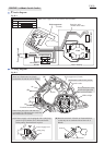
5) Remove Ring 17 from Bearing box section using 1R004 and 1R008.
(Fig. 24)
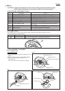
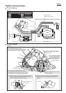
6) Fix Bearing box section in vise, then remove Bearing retainer 23-36
from Bearing box using 1R316 as illustrated in Fig. 25.
Ball bearing 6003DDW can now be removed.
Note: When fixing Bearing box section in vise, attach 1R041 to vise
in order not to damage Bearing box.
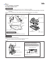
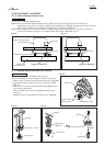
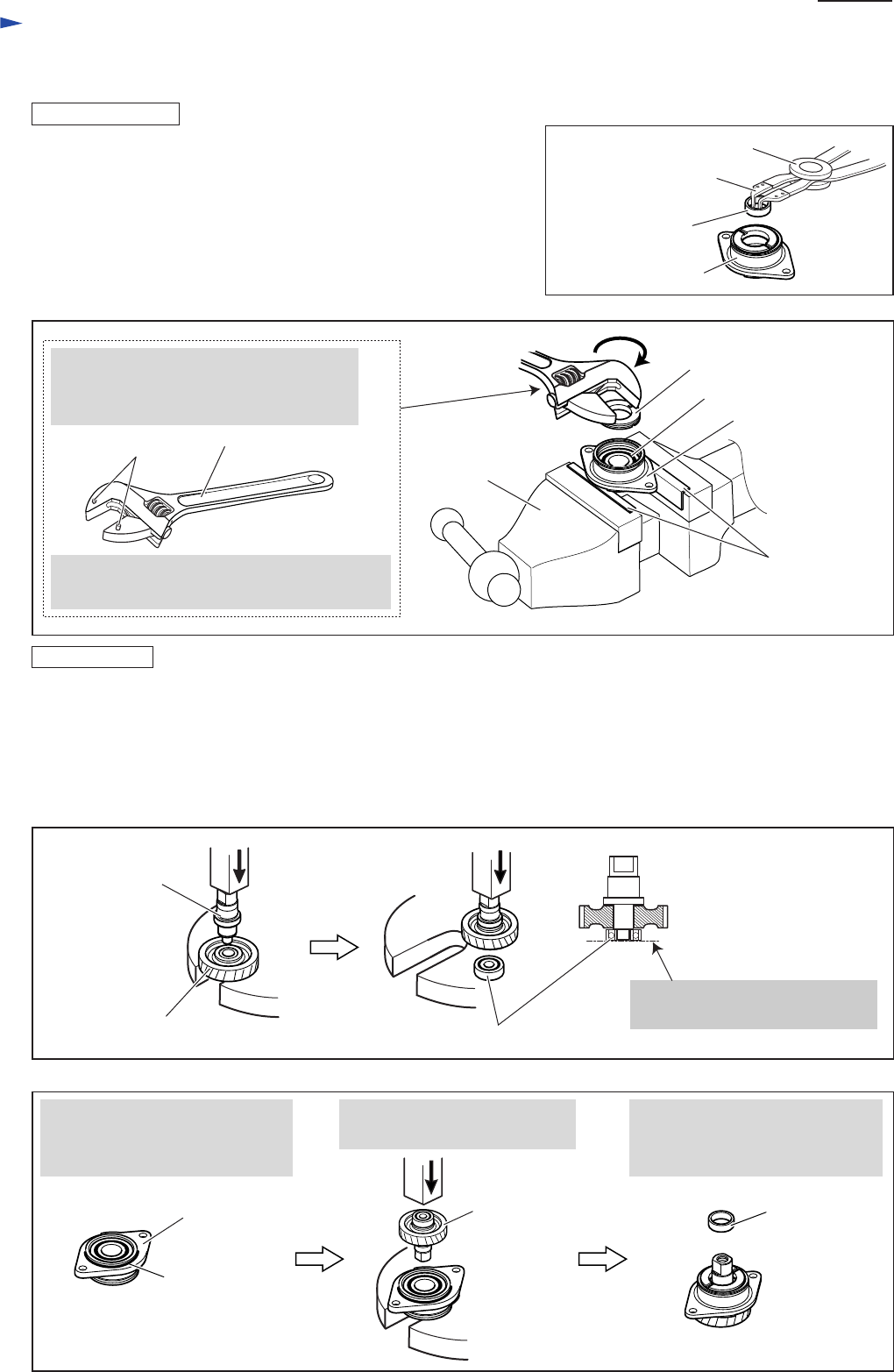
1) Fit Ball bearing 6003DDW in Bearing box, then mount Bearing retainer 23-36 on Bearing box by turning it
counterclockwise using 1R316 or 1R340.
2) Assemble Spindle to Helical gear 47 using arbor press. Then assemble Ball bearing 608LLB to them using arbor press.
(Fig. 26)
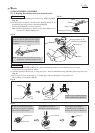
3) Set O ring 46 in place on Bearing box. Assemble Gear section to Bearing box using arbor press.
Then put Ring 17 on Spindle. (Fig. 27)
Bearing retainer 23-36
Ball bearing 6003DDW
O ring 46
Gear section
Ring 17
Vise
1R041
1R316
Pin
Fit the two pins of 1R316 into the notches
of Bearing retainer 23-36 and turn 1R316
clockwise.
Note: 1R340 can also be used for removal/
installation of Bearing retainer 23-36.
1R008
1R004
Ring 17
Bearing box section
Fig. 24
Fig. 25
Align the end of Spindle with the
surface of Ball bearing 608LLB.
Ball bearing 608LLB
Assemble Gear section to
Bearing box using arbor press.
Do not forget to put Ring 17
on Spindle before assembling
Bearing box section to Blade case.
Be sure to set O ring 46 in place
on Bearing box before assembling
Gear section to Bearing box.
Helical gear 47
Spindle
Fig. 26
Fig. 27
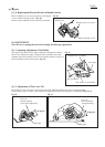
ASSEMBLING
DISASSEMBLING
Bearing box
Bearing box