


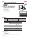
P 6/10
Repair
[3] DISASSEMBLY/ASSEMBLY
[3] -4. Motor Housing Section (cont.)
[3] -5. Bearing Box Section and Gear Section
ASSEMBLING
Do the reverse of the disassembling steps.
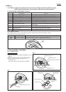
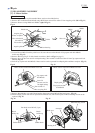
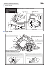
Note 1: Be sure to assemble Motor housing section to Blade case while pressing Shaft lock in the direction of
the black arrow to position the stopper of Shaft lock inside Blade case. (Fig. 16) Armature shaft cannot be locked
if the stopper of Shaft lock is positioned outside Blade case as illustrated in Fig. 17.
Note 2: When securing Lever 56 (the one used for cut depth setting) with Bow stop ring E-12, be sure to position the
concave side of Bow stop ring E-12 on Motor housing side. (Refer to Fig. 10 on page 4.)
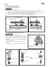
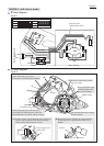
1) Remove Safety cover. See Figs. 1, 2, 3 on page 2.
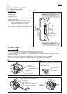
2) Remove Bearing box section together with Gear section from
Blade case by unscrewing two M5x16 Pan head screws. (Fig. 18)
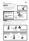
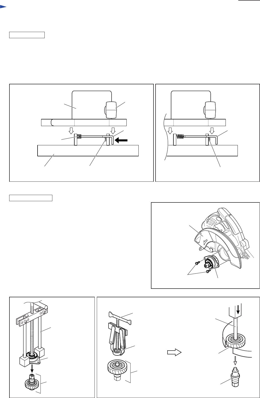
3) Separate Bearing box section from Gear section using 1R045.
(Fig. 19)
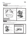
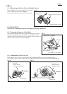
4) Turn over Gear section, and remove Ball bearing 608LLB from
Gear section using 1R269.
Then put 1R236 on the top end of Spindle and press it using
arbor press.
Spindle can now be separated from Helical gear 47. (Fig. 20)
Fig. 19 Fig. 20
Fig. 18
Blade case,
viewed from top
stopper of Shaft lock
Shaft lock
Motor housing section,
viewed from top
Front grip
Compression spring 9
Fig. 16
Pan head screw
M5x16 (2pcs)
Bearing box section
Blade case
Bearing box section
Gear section
Ball bearing
608LLB
1R045
1R269
1R236
Spindle
Helical gear 47
Fig. 17
DISASSEMBLING
stopper of Shaft lock
Shaft lock
Gear section