


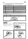
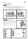
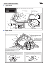
Circuit diagram
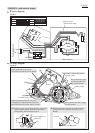
Wiring diagram
P 9/10
Protective tube
(Varnish tetron tube)
Note: Noise suppressor is not used for some countries.
Red
Black
White
Terminal block
LED Job light
Field
Switch
Fig. D-1
Color index of lead wires' sheath
Power supply cord
Noise suppressor
(if used)
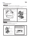
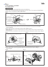
5008MG (without electric brake)
Motor housing
Handle
Switch
rib
Noise suppressor (if used)
Protective tube
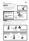
Fig. D-2
LED Job light
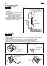
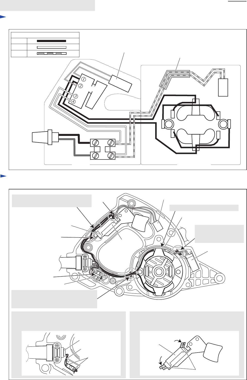
[A] If Power supply cord is equipped with a string loop,
put the loop around the ribs as illustrated below
before putting Terminal block in place.
[B] Bend the terminals of Switch as illustrated below
so that they do not touch the rib and the wall of
Handle.
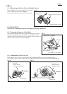
Put Protective tube in this portion.
Fix two lead wires (red)
to LED Job light with
this lead wire holder.
Route two Field lead wires (black)
between the rib and the wall of Handle.
When fixing lead wires with this lead
wire holder, fix LED lead wires (red) first,
then Field lead wires (black).
Terminal block
[A]
rib
string loop
Power supply cord
[B]
[B]
Switch
terminal
black/brown
white/blue