


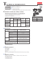
P 10/ 15
Repair
[3] DISASSEMBLY/ASSEMBLY
[3] -6. Switch Mechanism (cont.)
ASSEMBLING
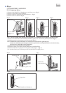
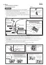
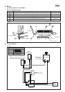
Fig. 38
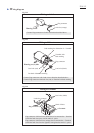
Fig. 39
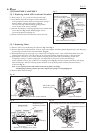
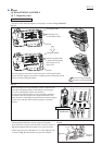
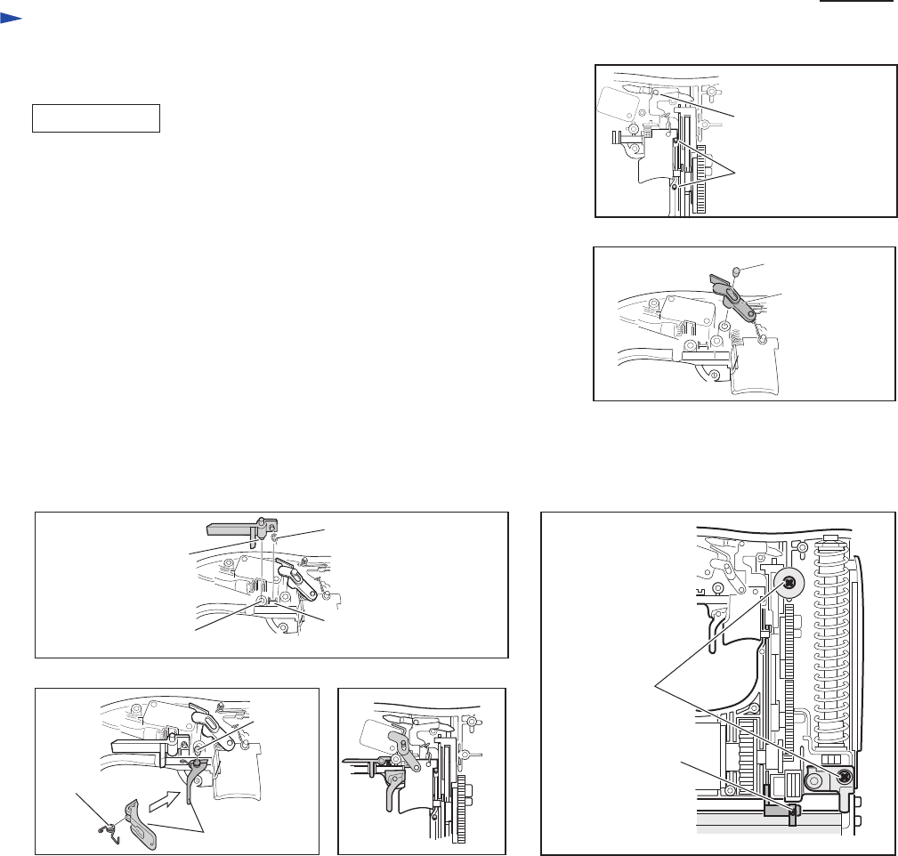
Fig. 43
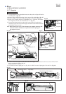
Fig. 41 Fig. 42
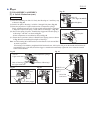
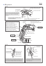
Fig. 40
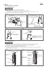
(7) Insert the remaining two Pins 2.5 firmly into Housing set L until they stop
as drawn in Fig. 38.
(8) Install Link plate to Housing L with Pin 3 through Link plate. (Fig. 39)
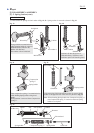
(9) Insert the projection of Light switch arm into Compression spring 2
firmly. And then insert the axis of Light switch arm into hole of Housing
L and push Compression spring 2 to the emboss of Housing L. (Fig. 40)
(10) Set Torsion spring 4 in place. Install Safety trigger and Torsion spring 4
to Housing L with Pin 3 as drawn in Fig. 41.
All the components are assembled as drawn in Fig. 42.
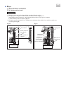
(11) Fasten the two positions with two Bind PT3x16 tapping screws as drawn
in Fig. 43 before assembling Housing R to Housing L.
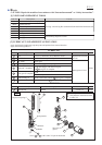
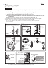
Note: Avoid loosening M3x4 Pan head screw that fastens Lock arm and Pin 5
as much as possible.
If loosening is inavoidable, pretighten M3x4 Pan head screw with Loctite 242 put on the thread and finish the all
reassembling work. After that, check the trigger’s smooth action and finally tighten the screw when the smooth
action can be obtained.
Pin 2.5 (2pcs.)
Pin 2.5
(Ref. Figs. 34 and 35)
Pin 3
Link plate
Compression spring 2
Emboss of Housing L
Torsion spring 4
M3x4 Pan
head screw
Bind PT3x16
tapping screw
(2pcs.)
Safety trigger
Pin 3
Axis of
Light switch arm
Hole of Housing L
for Light switch arm