


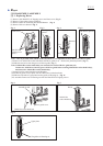
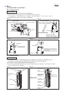
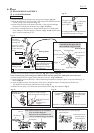
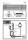
Switch put under ON-OFF Switch
(for Upper dead point detection)
Boss A
Lead wire (black) for connecting ON-OFF switch
and Upper dead point detection switch
Lead wire
holder A
Lead wire
holder A
Guide Lead wire (red) of Upper dead point
detection switch to DC motor while passing
the wire between boss A and lead wire
holder A.
Fix lead wire (black) of ON-OFF switch
with lead wire holder A.
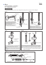
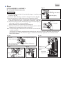
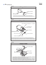
Switch (for ON-OFF) put on
Upper dead point detection switch
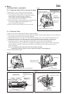
LED circuit
Rib B
Rib A
to Switch for
LED circuit
to Terminal
Lead wires (red and black) of LED circuit pass
between Rib A and Rib B so as not to put them
on the LED circuit.
Switch for LED circuit
Light switch arm
Terminal
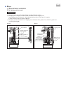
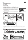
Lead wire holder B
Lead wire holder B
DC motor
LED lead wire (red)
[It is thinner than
Lead wire (red) of
Upper dead point
detection switch.]
Lead wire (red) of
Upper dead point
detection switch
Wall of Housing L
Pile lead wire (red) of Upper dead point detection switch
on LED lead wire (red), and then pass these lead wires
between lead wire holder B and the wall of Housing L.
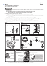
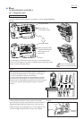
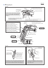
Rib
Pass the following lead wires between rib
and inner wall of Housing L.
*Lead wire (orange) for connecting
ON-OFF switch with terminal
*Lead wire (orange) for connecting
Switch for LED circuit with Terminal
*Lead wire (red) for connecting
LED circuit with Switch for LED circuit
*Lead wire (red) for connecting
Start point regulator and DC motor
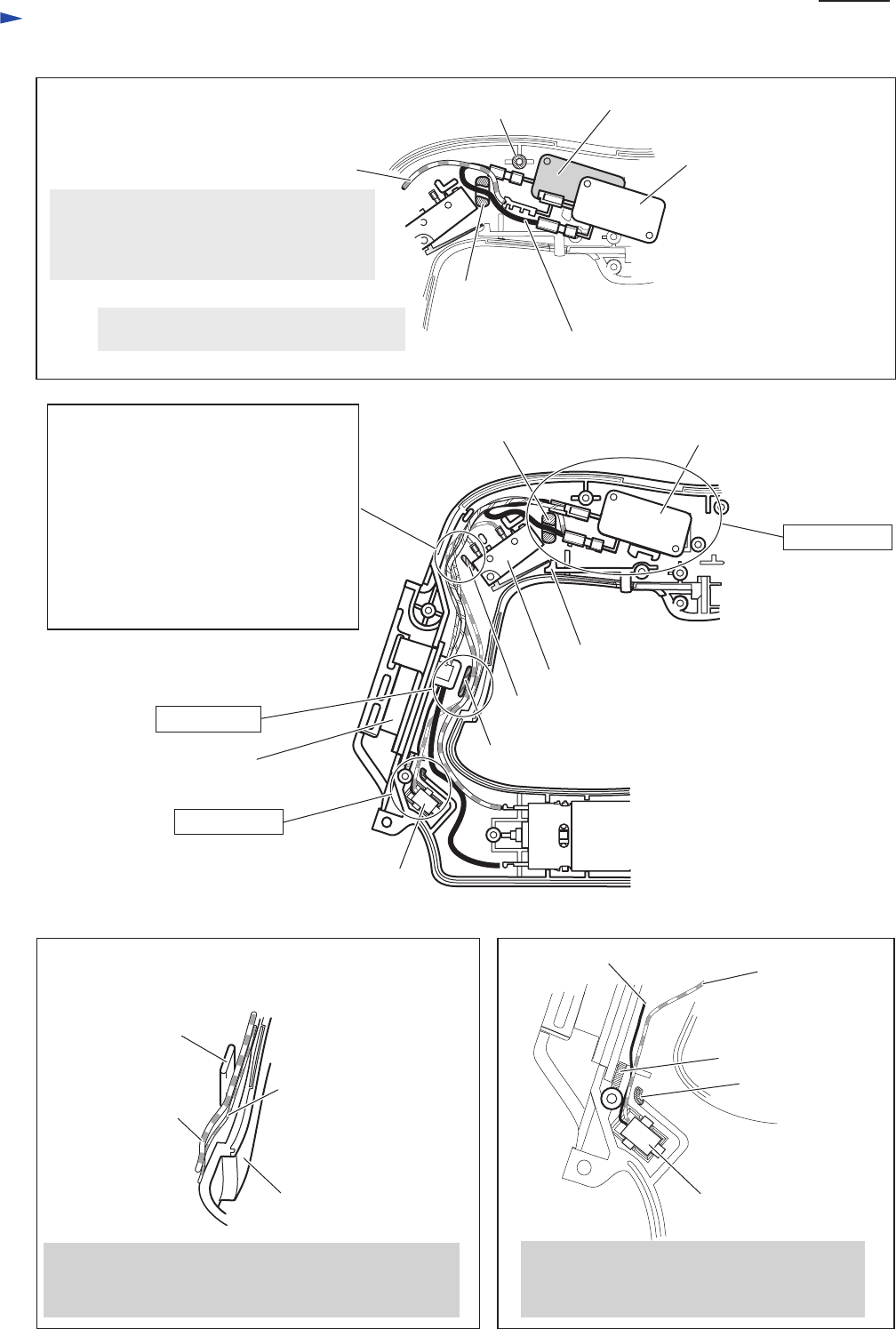
LED circuit
Switch (for ON-OFF)
See Fig. D-5.
See Fig. D-6.
See Fig. D-7.
Fig. D-5
Fig. D-6 Fig. D-7
P 15/ 15
Lead wire (red)
to + Terminal of
DC motor
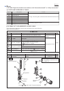
Wiring diagram