


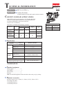
P 9/ 15
Repair
[3] DISASSEMBLY/ASSEMBLY
[3] -6. Switch Mechanism
ASSEMBLING
Fig. 33
Fig. 34 Fig. 35
Fig. 36
Fig. 37
Trigger
Trigger
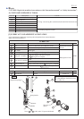
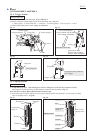
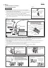
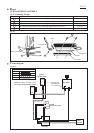
(1) Insert Guide plate and Compression spring 4 into Trigger. (Fig. 32)
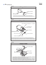
(2) Hook the short end of Torsion spring 3 with Swing arm, and then insert the
Torsion spring 3 into Swing arm. (Fig. 33)
(3) Insert Swing arm into Guide plate so that Pin 2.5 can be passed through
the grooves of Guide plate in the next step. (Figs. 32 and 33)
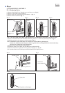
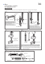
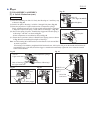
(4) Pass Pin 2.5 through the holes of Trigger and the grooves of Guide plate
while setting two Torsion springs 3 as drawn in Figs. 14 and 33 and secure
Pin 2.5 with two Stop rings E-2.0.
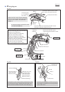
(5) Hook one Torsion spring 3 with the other (Ref. Fig. 33) as drawn in Fig. 34.
Note: Torsion spring 3 for Swing arm is different from Torsion spring 3 for Guide plate and Switch arm.
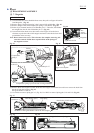
(6) Hook the projection of Trigger with the notch of Lock arm. (Figs. 34 and 35)
(7) Install Trigger section in Housing L while compressing Compression spring 4 to put it on the rib of Housing L as
drawn in Fig. 35.
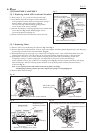
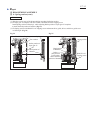
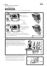
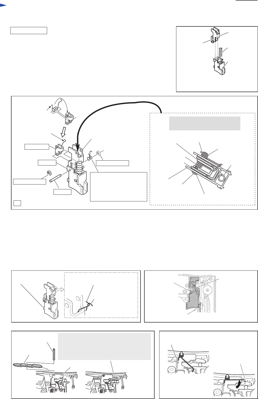
(8) After putting Switch arm in Guide plate, insert Pin 2.5 through the holes of Guide plate and Switch arm.
Pay attention to the direction of Switch arm. Refer to Fig. 36.
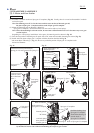
(9) Install Torsion spring 4 for Guide plate and Switch arm (Ref. Fig. 33) as drawn in Fig 37.
Compression
spring 4
Pin 2.5
: The components of Trigger set
Pin 2.5
Swing arm
long end of Torsion
spring 3 for hooking
the other Torsion
spring 3
Guide plate
Guide plate
Viewed from the upper side of
the assembled Trigger Section
Torsion spring 3 between
Trigger and Stop ring E-20
(Hook the shot end to
the projection of Trigger.
Refer to Fig. 14.)
Torsion spring 3
Stop ring E-2.0
Stop ring E-2.0
Stop ring E-2.0
Long end of Torsion spring 3
(come from inside of Swing arm)
Projection of Trigger hooked with notch of Lock arm
Compression
spring 4
Rib of Housing L
for compression
spring 4
long end of Torsion
spring 3
(located out of
Trigger)
Torsion spring 3
Swing arm
Housing R side
Housing L side
Housing L side
Housing R side
Fig. 32
Trigger
The groove
of Guide plate
to pass Pin 2.5
Inserting position of Guide plate and
Compression spring 4 to Trigger
Compression
spring 4
short end of
Torsion spring 3
for Swing arm
Projection of Trigger
(for Lock arm)
Note: Switch arm has to be assembled
so as to contact Push pin.
Otherwise, the machine does not
run even if Switch trigger is pulled.
(1) Put short end of Torsion spring 4
on Guide plate.
(2) Put short end of
Torsion spring 4
on Guide plate.
Pin 2.5
Guide plate
Switch arm
Stop ring E-2.0
Guide plate