


. A complete Parts List is available on-line at www.MillerWelds.com
OM-225 311 Page 13
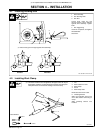
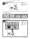
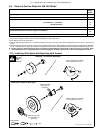
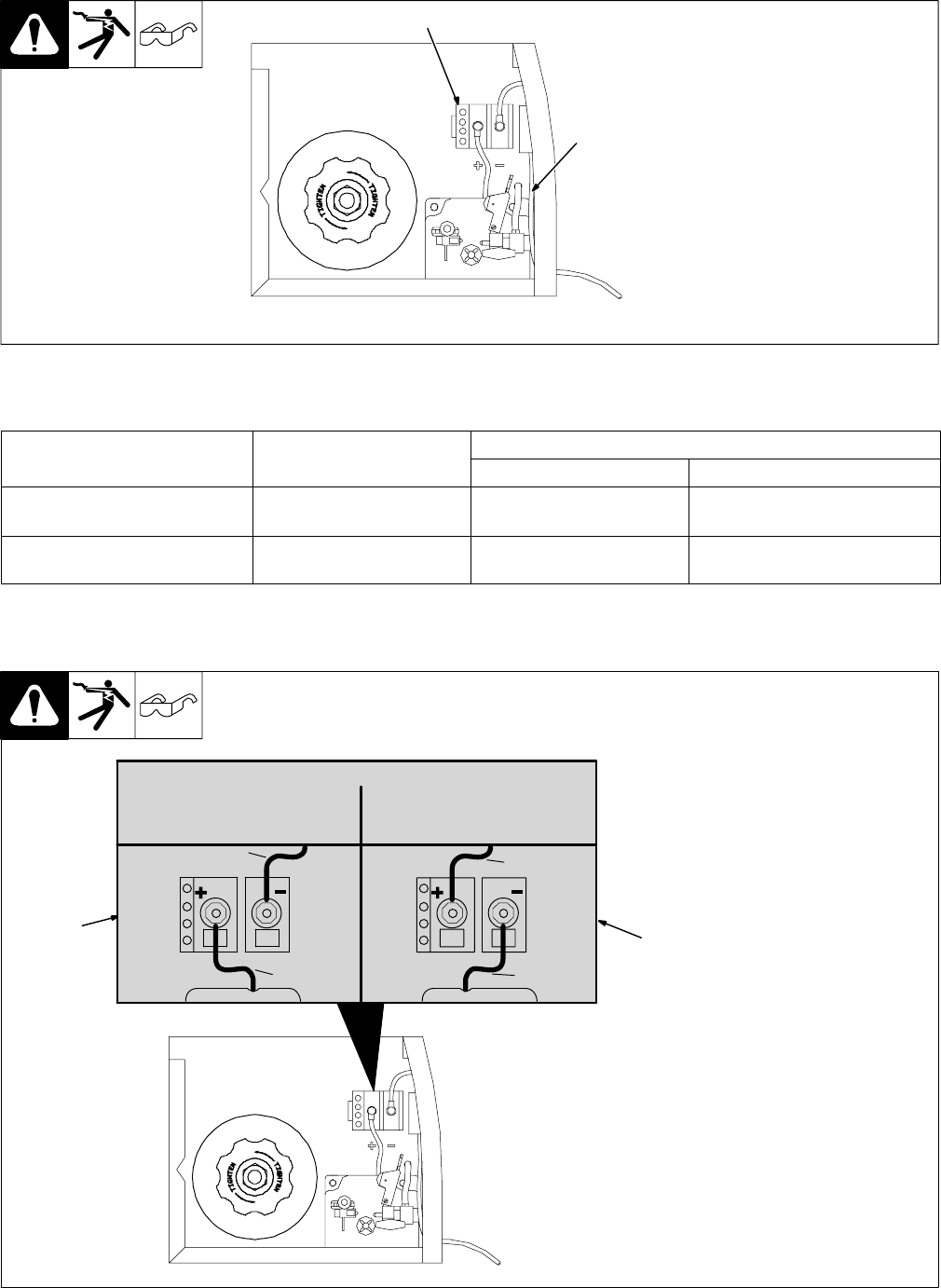
4-3. Work Cable Routing Inside Unit
Ref. 802 982-A
1 Work Cable
2 Output Terminal Block
Insert work cable through opening
in front panel and route along back
of front panel to output terminal
block.
Close door.
2
1
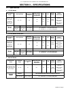
4-4. Process/Polarity Table
Process
Polarity
Cable Connections
Process
Polarity
Cable To Gun Cable To Work
GMAW − Solid wire with shield-
ing gas
DCEP − Reverse polarity Connect to positive (+) out-
put terminal
Connect to negative (−) output
terminal
FCAW − Self-shielding wire −
no shielding gas
DCEN − Straight Polarity Connect to negative (−)
output terminal
Connect to positive (+) output
terminal
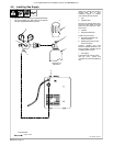
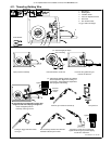
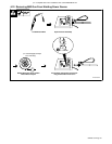
4-5. Changing Polarity
1 Lead Connections For Direct
Current Electrode Positive
(DCEP)
2 Lead Connections For Direct
Current Electrode Negative
(DCEN)
Always read and follow wire
manufacturer’s recommended
polarity, and see Section 4-4.
Close door.
1
Ref. 203 501 / Ref. 802 982-
2
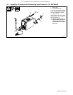
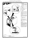
CHANGING POLARITY
DCEP
Electrode POSITIVE
FOR SOLID WIRE
DCEN
Electrode Negative
Flux Core Wire
WorkClamp
Lead
WireDrive
Lead
WorkClamp
Lead
WireDrive
Lead
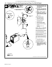
CHANGING POLARITY
DCEP
Electrode Positive
FOR SOLID WIRE
DCEN
Electrode Negative
Flux Core Wire
WorkClamp
Lead
WireDrive
Lead
WorkClamp
Lead
WireDrive
Lead
. Connection hardware must be tightened with proper tools. Do not
just hand tighten hardware. A loose electrical connection will cause
poor weld performance and excessive heating at the terminal block.