


. A complete Parts List is available on-line at www.MillerWelds.com
OM-225 311 Page 22
SECTION 5 − OPERATION
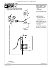
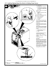
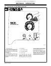
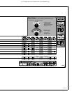
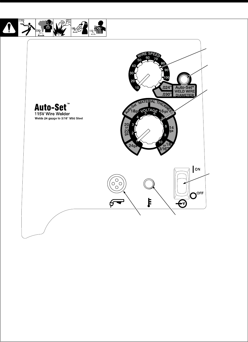
5-1. Controls For 115 VAC Model w/Auto-SetE
1 Wire Speed Control
Turn control clockwise inside white scale
(10-100) to increase wire feed speed. (see
weld parameter chart in welding power
source or Section 5-4, 5-5, 5-6, 5-7, or 5-8
as applicable).
2 Voltage Control
Turn control clockwise inside white scale
(1-10) to increase voltage (see weld
parameter chart in welding power source
or Section 5-4, 5-5, 5-6, ,5-7, or 5-8 as
applicable).
3 Power Switch
4 Over Temperature Light
5 Gun Trigger Receptacle
6 Auto−Set Light
To use Auto−Set mode, rotate Wire
Speed control inside blue area for the
applicable Weld Wire Diameter,
Auto−Set light will turn on, and the unit will
provide the appropriate wire feed speed for
the material thickness selected using the
Voltage control (see Section 5-4).
Rotate Voltage control inside blue scale (24
ga to 1/8”) for the applicable material
thickness and the unit will provide the
appropriate voltage within the range of the
selected material thickness and the selected
Weld Wire Diameter (see Section 5-4).
227 748-C
1
2
3
4
5
6