


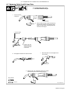

. A complete Parts List is available on-line at www.MillerWelds.com
OM-225 311 Page 35
232 017-A
232 017-A
2.5/10
2/22
2.5/15
2.5/15
3/20
2.5/28
2.5/15
3.5/20
3.5/10
3.5/30
1/15
1/15
3/30
3.5/20
3.5/25
4/10
4/10
4/40
4/20
4/25
4/10
3.5/15
4.5/40
4/50
5/50
5/50
5/25
4/40
4/35
4/20
4.5/70
4.5/35
5.5/60
7/100
6/50
6/25
6/45
6/30
5.5/65
6.5/40
5.5/50
6.5/55
7.5/50
6.5/55
6.5/30
5.5/60
10/50
6.5/70
6/35
7/60
10/40
10/20
10/45
10/60
6/85
5/50
5.5/55
5.5/35
5/70
4.5/45
5/40
4.5/30
4.5/40
5/65
3/15
3/20
3/30
5/20
5/25
4/30
4.5/40
4/35
5/45
4/25
4/25
4/25
4/40
4.5/20
4/18
2/20
2/20
2/10
3.5/452.5/28
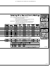
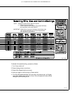
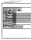
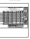
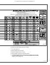
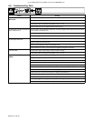
NOTE: Settings are approximate. Adjust as required.
“−−−” Means not recommended.
“*” Thicker materials can be welded using proper technique,
joint preparation and multiple passes.
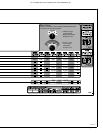
IMPORTANT: Match drive roll groove to diameter of wire being used. Set Tension
knob setting to 3 at start. Adjust tension per instructions in the manual.
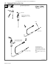
.045” (1.2 mm) #202926
.024” (0.6 mm) #220179
.030” (0.8 mm) #220179 #202926
.035” (0.9 mm) #220179 #202926
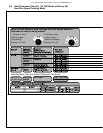
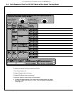
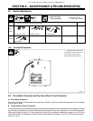
To disable wire speed tracking, proceed as follows:
1. Turn Power switch off.
2. Rotate Voltage knob to maximum.
3. Rotate Wire Speed knob to minimum.
4. Hold gun trigger in while turning on Power switch.
. To verify wire speed tracking is off, open drive roll pressure arm, pull trigger,
and rotate Voltage knob from min. to max. Drive roll speed will have minimal
change in rpm if tracking is off.