


. A complete Parts List is available on-line at www.MillerWelds.com
OM-225 311 Page 20
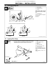
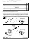
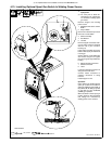
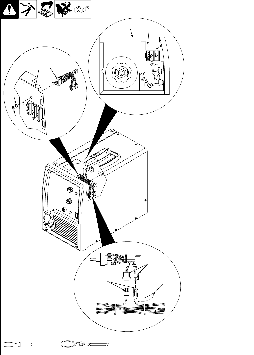
4-13. Installing Optional Spool Gun Switch In Welding Power Source
Ref. 804 984-A / 804 892-A
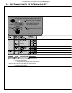
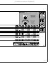
Tools Needed:
1/4, 5/16 in
9/16 in
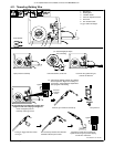
Y Turn Off unit, and disconnect
input power.
. For units prior to Serial No.
LH210051N, use retrokit part
no. 234402 for installing spool
gun switch.
Remove wrapper from welding
power source.
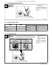
1 Welding Power Source Center
Baffle
2 Snap-in Blank
Remove and discard snap-in blank
from hole in center baffle.
3 Switch Assembly
4 Star Washer
5 Jam Nut
Remove top jam nut and star wash-
er from switch (switch is equipped
with two nuts, a jam nut and a
backing nut).
Insert switch assembly into center
baffle so that keyway in switch shaft
is facing up.
Secure switch to center baffle with
star washer and jam nut. Tighten
jam nut enough to keep switch from
rotating.
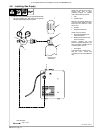
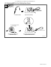
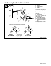
6 Wiring Harness Connectors
7 Switch Connectors
8 Label
Locate and separate connectors in
wiring harness near label.
Connect switch connectors to
matching connectors in wiring
harness.
Install wrapper on unit.
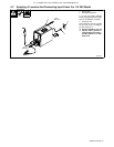
Operation:
Place switch in the position with the
spool gun symbol on the label for
spool gun operation. Place switch in
the position with the MIG gun symbol
on the label for wire feeder/MIG
(GMAW) gun operation.
When the switch is in the spool gun
position, spool gun wire feed speed
and voltage are controlled by
welding power source controls.
2
1
7
6
4
3
1
5
8