


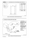


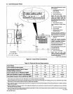


B.
Connecting
Input
Power
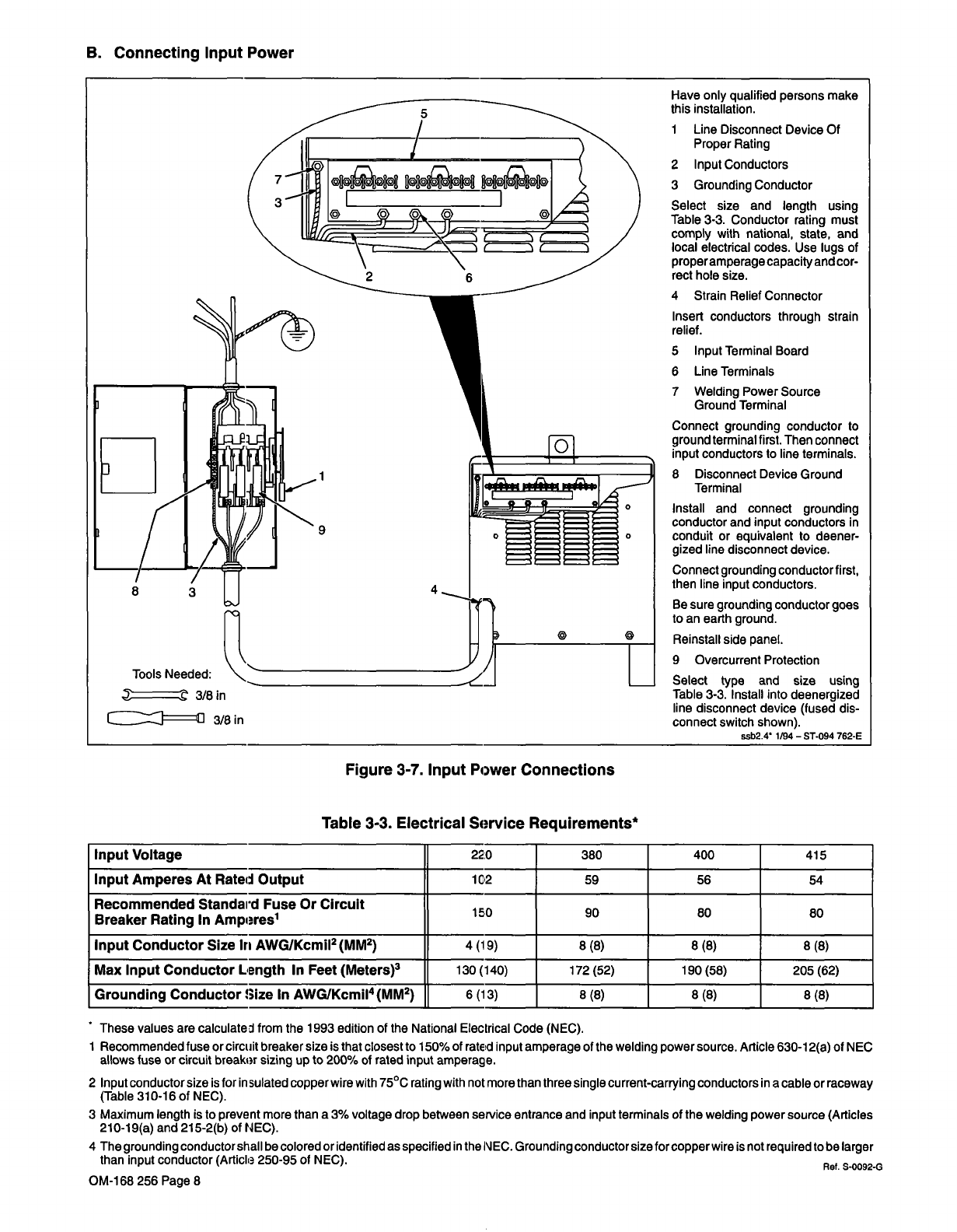
Figure
3-7.
Input
Power
Connections
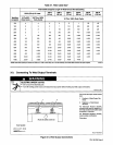
Table
3-3.
Electrical
Service
Requirements*
Input
Voltage
220
380
400
415
Input
Amperes
At
Rated
Output
1C2
59
56
54
Recommended
Standard
Fuse
Or
Circuit
Breaker
Rating
In
Amperes1
lEO
90
80
80
Input
Conductor
Size
In
AWGIKcmII2
(MM2)
4
(19)
8
(8)
8
(8)
8
(8)
Max
Input
Conductor
Length
In
Feet
(Meters)3
130(140)
172
(52)
190(58)
205
(62)
Grounding
Conductor
Size
In
AWGIKcmiI4
(MM2)
6
(13)
8
(8)
8
(8)
8
(8)
These
values
are
calculated
from
the
1993
edition
of
the
National
Electrical
Code
(NEC).
1
Recommended
fuse
or
circuit
breaker
size
is
that
closest
to
150%
of
ratEd
input
amperage
of
the
welding
power
source.
Article
630-12(a)
of
NEC
allows
fuse
or
circuit
breaker
sizing
up
to
200!.
of
rated
input
amperage.
2
Input
conductor
size
is
for
insulated
copper
wire
with
75C
rating
with
not
more
than
three
single
current-carrying
conductors
in
a
cable
or
raceway
(Table
31
0-16
of
NEC).
3
Maximum
length
is
to
prevent
more
than
a
3%
voltage
drop
between
service
entrance
and
input
terminals
of
the
welding
power
source
(Articles
210-19(a)
and
215-2(b)
of
NEC).
4
The
grounding
conductorshall
be
colored
or
identified
as
specified
in
the
NEC.
Grounding
conductor
size
forcopperwire
is
not
required
to
be
larger
than
input
conductor
(Article
250-95
of
NEC).
Ref
S-0092-G
OM-168
256
Page
8
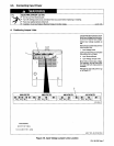
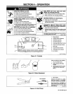
Have
only
qualified
persons
make
this
installation.
1
Line
Disconnect
Device
Of
Proper
Rating
2
Input
Conductors
3
Grounding
Conductor
Select
size
and
length
using
Table
3-3.
Conductor
rating
must
comply
with
national,
state,
and
local
electrical
codes.
Use
Iugs
of
properamperage
capacity
and
cor
rect
hole
size.
4
Strain
Relief
Connector
Insert
conductors
through
strain
relief.
5
Input
Terminal
Board
6
Line
Terminals
7
Welding
Power
Source
Ground
Terminal
Connect
grounding
conductor
to
ground
terminal
first.
Then
connect
input
conductors
to
line
terminals.
8
Disconnect
Device
Ground
Terminal
Install
and
connect
grounding
conductor
and
input
conductors
in
conduit
or
equivalent
to
deener
gized
line
disconnect
device.
Connect
grounding
conductor
first,
then
line
input
conductors.
Be
sure
grounding
conductor
goes
to
an
earth
ground.
Reinstall
side
panel.
9
Overcurrent
Protection
Select
type
and
size
using
Table
3-3.
Install
into
deenergized
line
disconnect
device
(fused
dis
connect
switch
shown).
ssb2.4
1/94
5T-094
762-E
Tools
Needed:
~
3/8
in
3/8
in