


a
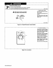
~JVARNING
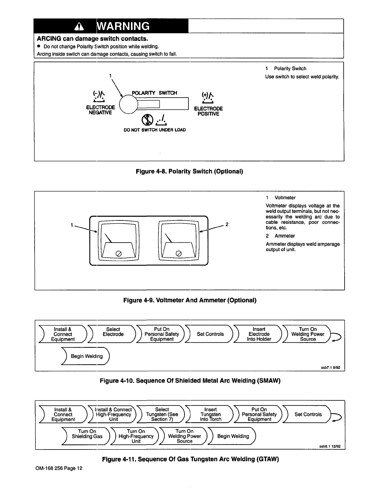
ARCING
can
damago
switch
contacts.
Do
not
change
Polarity
Switch
position
while
welding.
Arcing
inside
switch
can
damage
contacts,
causing
switch
to
fail.
Li
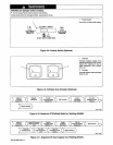
Figure
4-8.
Polarity
Switch
(Optional)
Figure
4-9.
Voltmeter
And
Ammeter
(Optional)
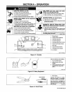
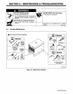
Figure
4-10.
Sequence
Of
Shielded
Metal
Arc
Welding
(SMAW)
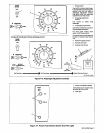
Figure
4-11.
Sequence
Of
Gas
Tungsten
Arc
Welding
(GTAW)
1
Polarity
Switch
1
Use
switch
to
select
weld
polarity.
(-)/%.
~~~OLARITY
SWITCH
(+)/~.
ELECTRODE
_______________
ELECTRODE
NEGATIVE
POSITIVE
DO
NOT
SWITCH
UNDER
LOAD
1
Voltmeter
Voltmeter
displays
voltage
at
the
weld
output
terminals,
but
not
nec
essarily
the
welding
arc
due
to
2
cable
resistance,
poor
connec
tions,
etc.
2
Ammeter
Ammeter
displays
weld
amperage
output
of
unit.
~\\
Insert
\
Install&
Connect
Electrode
Personal
Safety
Set
Controls
)
Electrode
}
Equipment
))I
Equipment
)~
~,J)
Into
Holder
)~we)
Select
))
Put
On
)
Begin
WeldiD
ssb7.1
9/92
Connect
High-Frequency
~
Tungsten
(See
Tungsten
Per
____________
Unit
J)
Section
7)
Into
Torch
))
Equipment
\
Install
&
j)~1stall
&
Connect~~
Select
)~
Insert
Put
On
))I~~~ntrolD.~
sonal
Safety
)
Equipment
____________
________________
______________
________________
On
Turn
On
Turn
O~I~)
Begin
WeIdin~)
)
Shielding
Gas
)
High-Frequen
Welding
Powe
______________
)
Unit
Source
ssb8.1
12/92
OM-168
256
Page
12