


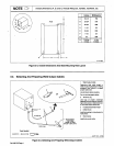
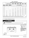
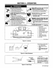

Figure
3-2.
Overall
Dim
ensions
And
Base
Mounting
Hol
e
Layout
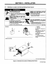
3-2.
Selecting
And
Preparing
Weld
Output
Cables
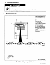
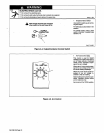
1
Weld
Output
Cable
Determine
total
cable
length
in
weld
circuit
and
maximum
welding
amperes.
Use
Table
3-1
to
select
proper
cable
size.
Use
shortest
cables
possible.
Do
not
use
damaged
cables.
2
Terminal
Lug
Use
lugs
of
proper
amperage
capacity
and
hole
size
for
connect
ing
to
work
clamp
or
electrode
hold
er,
and
weld
output
terminals.
3
Insulated
Electrode
Holder
4
GTAW
Torch
Install
according
to
manufacturers
instructions.
For
Example,
Total
Cable
Length
In
Weld
Circuit
=20
ft
(6
m)
5
Work
Clamp
Install
onto
work
cable.
Tools
Needed:
z=~
sD6.5
11192
S-0752
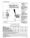
Figure
3-3.
Selecting
And
Preparing
Weld
Output
Cables
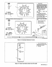
Inches
Millimeters
A
30-1/4
769
Front
B
22-3/4
578
0
~
r-
C
35-3/4
908
D
1-1/2
38
E
32-3/4
832
F
1-1/8
29
G
20 508
H
7I16Dia.
4
Holes
11
Dia.
4
Holes
~-
G
F
ST-153
NOTE
~
Overall
dimensions
(A,
B,
and
C)
include
lifting
eye,
handles,
hardware,
etc.
OM-168
256
Page
4