


OM-216 244 Page 19
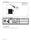
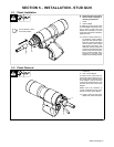
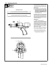
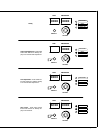
The lift controls the arc length and is a factor
in controlling the heat of the welding process.
Lift should be set at 3/32 or .094 in (2.5 mm).
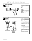
Measuring LIft
Y For safety from accidental activation,
always disconnect the weld cable
from the power source before making
any stud gun adjustments or per-
forming any service on the stud gun.
1 Stud Lift Measurement
To measure stud lift, hold a scale against
some fixed part of the tool. The front cover or
foot will work well. Press the trigger so the
tool activates the lift mechanism. Now mea-
sure again. The lift is the difference between
the two measurements.
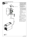
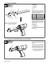
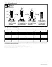
Adjusting Lift
2 Location of Core Set Screws
To adjust lift, remove the slotted screw hold-
ing the rear cap in place. Remove rear cap.
Loosen the nylon tipped set screw that holds
the adjustable core in place. To increase lift,
turn the adjustable core screw counter
clockwise. To decrease lift, turn the adjust-
able core screw clockwise. Each half turn
equals .025 in (0.6 mm).
Once lift is set, retighten nylon tipped set
screw to keep the adjustable core in place.
Install rear cap and tighten cap screw.
. Keep cap in place to prevent dirt from en-
tering the stud gun mechanism
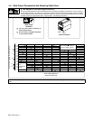
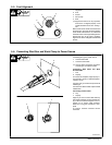
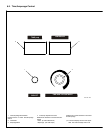
5-8. Adjusting Stud Lift
2
1/16 in (1.6 mm) lift for studs up to 5/16 (7.9 mm) diameter
3/32 in (2.4 mm) lift for studs over 5/16 (7.9 mm) to 1/2 in (13 mm) diameter
1/8 in (3.2 mm) lift for studs over 1/2 (13 mm) diameter
LIft Adjustment Table
2
1