


OM-4401 Page 9
SECTION 2 – DEFINITIONS
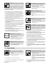
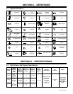
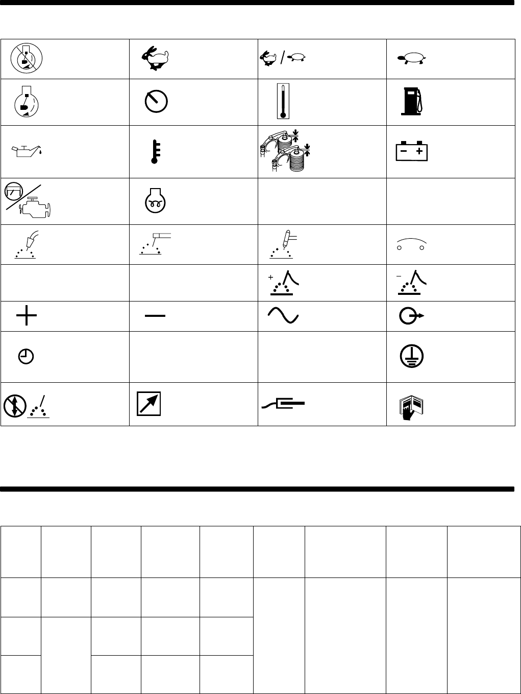
2-1. Symbol Definitions
Stop Engine
Fast
(Run, Weld/Power)
Fast/Slow
(Run/Idle)
Slow (Idle)
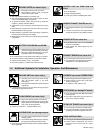
Start Engine Panel/Local Temperature Fuel
Engine Oil High Temperature
Check Valve
Clearance
Battery (Engine)
Engine Glow Plug
A
Amperes
V
Volts
MIG (GMAW),
Wire
Stick (SMAW) TIG (GTAW) Circuit Breaker
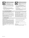
CC
Constant Current
CV
Constant Voltage
Electrode
Positive
Electrode Negative
Positive Negative
Alternating Current
(AC)
Output
Time
h
Hours
s
Seconds
Protective Earth
(Ground)
Do not switch while
welding
14
Remote 14
Receptacle
Work Connection
Read Operator’s
Manual
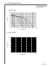
SECTION 3 – SPECIFICATIONS
3-1. Weld, Power, And Engine Specifications
Welding
Mode
Rated
Welding
Output At
Weld
Speed
Rated
Welding
Output At
Idle Speed
Maximum
Open-Circuit
Voltage
Amperage
Range In
CC Mode
Voltage
Range In
CV Mode
Generator
Power Rating
Fuel
Capacity
Engine
CC/AC
200 A,
25 V, 60%
Duty Cycle
–– 75 40 – 225 A
Peak: 12 kVA/kW
CC/DC
350 A,
28 V, 60%
Duty Cycle
180 A, 28
V, 100%
Duty Cycle
80 20 – 350 A
10 – 34 V
Continuous:
Single-Phase,
10 kVA/kW
50/41.6 A,
13 gal(49 L)
Tank
Kubota DH905
Water-Cooled,
Three-Cylinder,
Four-Cycle,
26 HP Diesel
CV/DC
300 A,
32 V, 100%
Duty Cycle
–– 50 ––
120/240 V AC,
60 Hz
26 HP Diesel
Engine