


OM-4401 Page 24
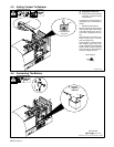
SECTION 6 – OPERATING AUXILIARY EQUIPMENT
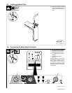
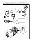
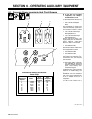
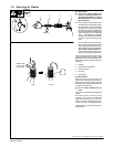
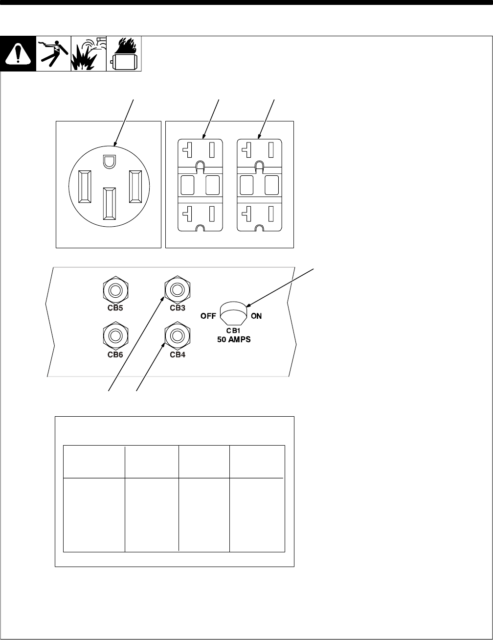
6-1. Generator Power Receptacles And Circuit Breakers
Ref. ST-203 031-A
1
Y If unit does not have GFCI
receptacles, use GFCI-pro-
tected extension cord.
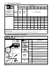
. Generator power decreases as
weld current increases.
1 240 V 50 A AC Receptacle
RC3
RC3 supplies 60 Hz single-phase
power at weld/power speed. Maxi-
mum continuous output is 10 kVA/
kW.
2 120 V 20 A AC GFCI Duplex
Receptacle GFCI-4
3 120 V 20 A AC GFCI Duplex
Receptacle GFCI-5
GFCI-4 and GFCI-5 supply 60 Hz
single-phase power at weld/power
speed. Maximum output from
GFCI-4 or GFCI-5 is 2.4 kVA/kW.
4 Circuit Breaker CB1
CB1 protects RC3, GFCI-4, and
GFCI-5 from overload. If CB1 opens,
the receptacles do not work.
5 Circuit Breaker CB3
6 Circuit Breaker CB4
CB3 protects GFCI-4 and CB4 pro-
tects GFCI-5 from overload. If a cir-
cuit breaker opens, the receptacle
does not work.
. Move switch (CB1) or press but-
ton (CB3, CB4) to reset circuit
breaker. If breaker continues to
open, contact Factory Autho-
rized Service Agent.
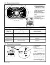
Combined output of all receptacles
limited to 10 kVA/kW rating of the
generator.
EXAMPLE: If 19 A is drawn from
each 120 V duplex receptacle, only
23 A is available at the 240 V
receptacle:
2 x (120 V x 19 A) + (240 V x 23 A) =
10 kVA/kW
Watts
Weld Current
Amperes
0
50
100
150
200
250
300
350
Simultaneous Welding And Generator
Power Output
240 V
Receptacle
Amperes
120 V
Receptacle
Amperes
23
12000
10900
9100
7600
6400
4000
1900
1000
50
50
50
50
50
34
16
8
50
46
38
32
27
17
8
4
4
56