


OM-4401 Page 21
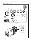
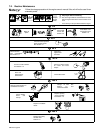
5-2. Description Of Controls (See Section 5-1)
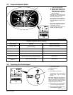
Engine Lights
1 Battery Charging Light
Light goes on if engine alternator is not charg-
ing battery. Engine continues to run.
Y Stop engine and fix trouble if Battery
Charging light goes on.
2 Engine Temperature Light
Light goes on and engine stops if engine tem-
perature is too high.
Y Stop engine and fix trouble if Engine
Temperature light goes on.
3 Engine Oil Pressure Light
Light goes on and engine stops if oil pressure
is too low. Light goes on momentarily during
start-up but goes out when engine reaches
normal oil pressure.
Y Stop engine and fix trouble if Engine
Oil Pressure light stays on after start-
up.
4 Glow Plug Light
LIght is not active on this model.
Glow plug warms in about six seconds and en-
gine can be started (see starting instructions
following).
Y Do not use glow plug longer than 20
seconds.
Engine Gauges
5 Engine Hour Meter
6 Fuel Gauge
Use gauge to check fuel level.
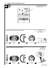
Weld Controls
7 Ammeter (Optional)
Meter displays weld amperage at the weld out-
put terminals, but not necessarily the welding
arc due to resistance of cables and connec-
tions.
8 Voltmeter (Optional)
Meter displays weld voltage at the weld termi-
nals, but not necessarily the welding arc due
to resistance of cables and connections.
9 DC Polarity/AC Selector Switch
Y Do not switch under load.
Use switch to select AC weld output or polarity
of DC weld output.
10 Process/Contactor Switch
See Section 5-3 for Process/Contactor switch
information.
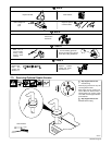
11 V/A (Voltage/Amperage) Adjust Switch
And Remote 14 Receptacle
For front panel control, place switch in Panel
position and use the V/A Adjustment control.
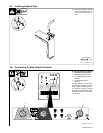
For remote control, make connections to Re-
mote 14 receptacle, and place switch in Re-
mote position (see Sections 4-8 and 5-5). The
value selected on V/A Adjustment control is
the maximum available at the remote.
. Set V/A Adjustment control (item12) to
max for MIG welding.
12 V/A (Voltage/Amperage) Adjustment
Control
With Process/Contactor switch in any Stick or
TIG setting, use control to adjust amperage.
With Process/Contactor switch in any MIG
position, use control to adjust voltage.
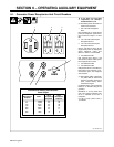
Engine Starting Controls
13 Engine Control Switch
Use switch to start engine, stop engine, and
operate glow plug for cold weather starting.
Glow plug warms in about six seconds and en-
gine can then be started (see starting instruc-
tions following).
14 Engine Speed Switch
Use switch to select engine speed.
Place switch in Idle position to lock engine at
idle speed during start-up, and to CC weld at
idle speed (up to 180 A). See Section 5-4 for
information on operating at idle speed.
In Run/Idle position, engine runs at idle speed
at no load and weld/power speed under load.
In Run position, engine runs at weld/power
speed.
. Place switch in Run or Run/Idle position
when using generator power.
. Place switch in Run position to operate
most GMAW equipment.
To Start:
Y Do not use ether as a starting aid.
Using ether voids warranty.
Above 325 F: turn Engine Speed switch to Idle
and Engine Control switch to Start. Release
Engine Control switch when engine starts and
Engine Oil Pressure light goes out.
. If engine does not start, let engine come
to a complete stop before attempting re-
start.
Below 325 F: turn Engine Speed switch to
Idle. Turn Engine Control switch to Glow Plug
position for about six seconds, and then turn
Engine Control switch to Start. Release switch
when engine starts and Engine Oil Pressure
light goes out. Do not crank engine while en-
gine is turning.
. If engine does not start, let engine come
to a complete stop before attempting re-
start.
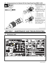
To Stop: turn Engine Control switch to Off
position.
. Push engine stop lever to stop engine if
Engine Control switch does not work (see
item 15).
15 Engine Stop Lever
Use lever to stop engine if Engine Control
switch does not work.