


OM-4401 Page 31
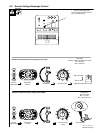
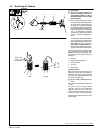
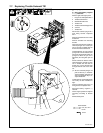
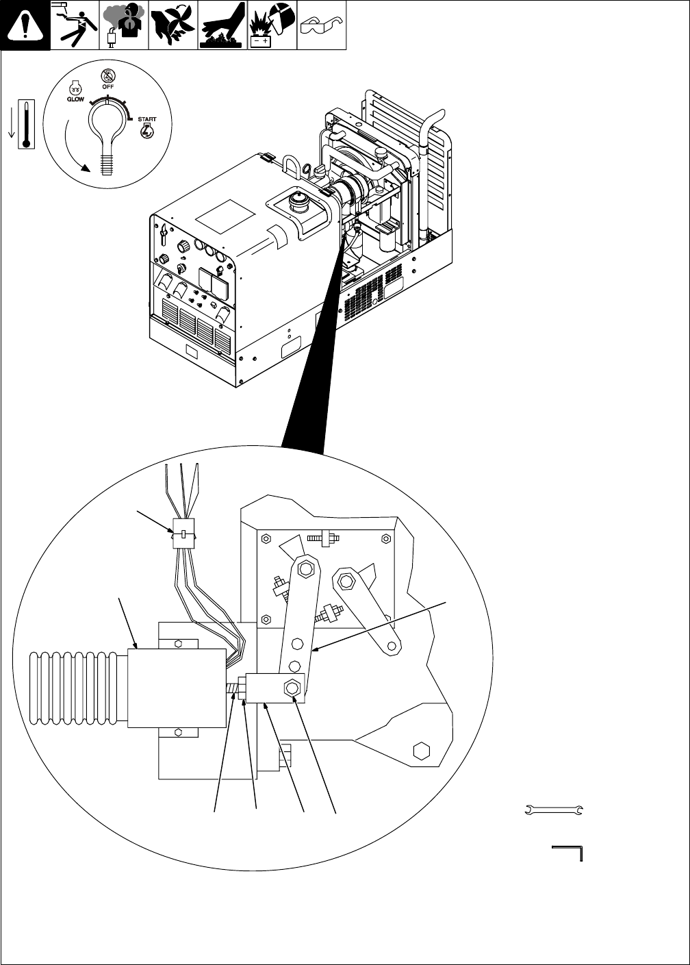
7-7. Replacing Throttle Solenoid TS1
Ref. 802 579-B
Y Stop engine, and let cool.
Y Disconnect battery, negative
(–) cable first.
Remove right side engine panel.
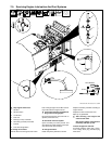
1 Plug PLG11/Receptacle RC11
2 Throttle Solenoid TS1
3 Shoulder Bolt And Nut
4 Throttle Link
5 Throttle Solenoid Plunger Rod
6 Jam Nut
7 Throttle Arm
Disconnect solenoid plug PLG11
from wiring harness receptacle
RC11.
Remove shoulder bolt and nut from
throttle link.
Remove solenoid from mounting
bracket.
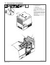
Note how much thread is visible on
solenoid plunger rod. Loosen jam
nut just enough so throttle link can
be removed from solenoid rod.
Install throttle link on new solenoid
plunger rod. Turn link until the same
amount of thread will be visible on
plunger rod when the jam nut is
tightened. (Do not tighten jam nut
yet.)
Mount solenoid on bracket. Move
solenoid plunger manually to align
slot in throttle link with hole in
throttle arm. Insert shoulder bolt
through slot/hole and secure with
nut.
. Be sure solenoid plunger rod
pulls all the way in “bottoms”
when energized. If plunger rod
does not pull all the way in, re-
adjust throttle link.
Tighten jam nut on solenoid plunger
rod. Verify all other hardware is
tight.
Connect solenoid plug PLG11 to
wiring harness receptacle RC11.
Reconnect battery, negative (–)
lead last.
Check engine speeds and adjust if
necessary according to Section
7-8.
Reinstall side panel.
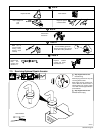
10 mm
Tools Needed:
7/16, 3/8, 1/2 in
7
2
6 345
3/16 in
1