


OM-4401 Page 14
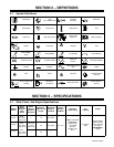
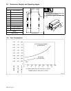
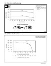
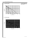
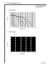
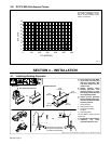
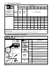
3-8. DC/CV MIG Volt-Ampere Curves
203 112
Volt-ampere curves show minimum
and maximum voltage and amper-
age output capabilities of unit.
Curves of other settings fall be-
tween curves shown.
0
5
10
15
20
25
30
35
40
45
0 100 200 300 400 500 600
DC AMPERES
DC VOLTS
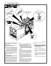
SECTION 4 – INSTALLATION
install1 10/00 – Ref. ST-800 652 / Ref. ST-800 477-A / ST-158 936-A / S-0854
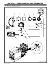
Y Do not weld on base. Weld-
ing on base can cause fuel
tank fire or explosion. Bolt
unit down using holes pro-
vided in base.
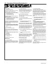
Y Always securely fasten
welding generator onto
transport vehicle or trailer
and comply with all DOT and
other applicable codes.
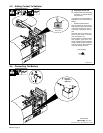
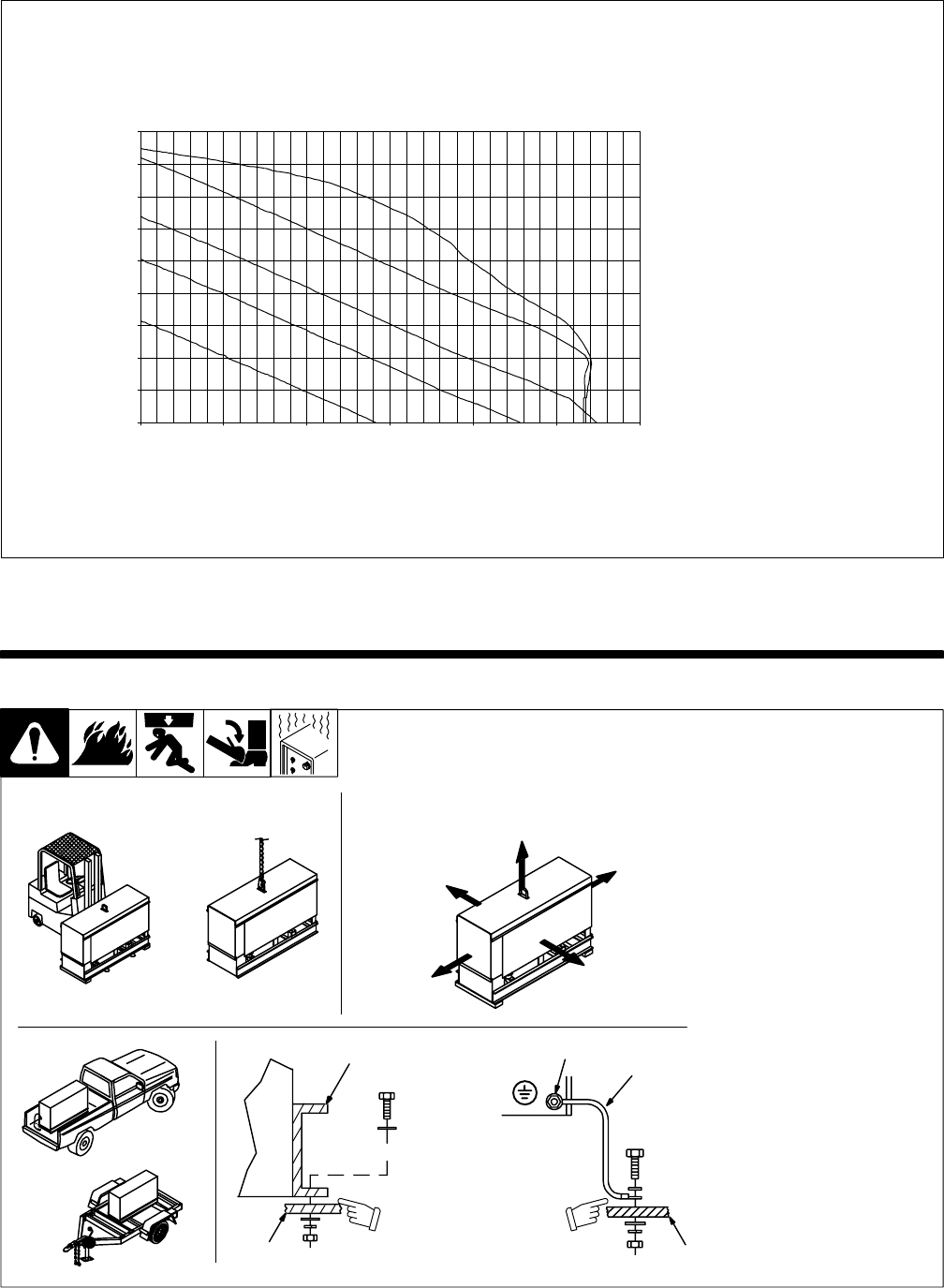
Y Always ground generator
frame to vehicle frame to pre-
vent electric shock and static
electricity hazards.
1 Generator Base
2 Metal Vehicle Frame
3 Equipment Grounding
Terminal
4 Grounding Cable
Use #10 AWG or larger insulated
copper wire.
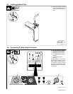
Y If unit does not have GFCI re-
ceptacles, use GFCI-
protected extension cord.
1
2
Electrically bond genera-
tor frame to vehicle frame
by metal-to-metal contact.
GND/PE
3
4
2
OR
OR
18 in
(460 mm)
18 in
(460 mm)
18 in
(460 mm)
18 in
(460 mm)
18 in
(460 mm)
OR
Movement Airflow Clearance
Location
Grounding
Y Do not lift unit from end.
4-1. Installing Welding Generator