


OM-4401 Page 22
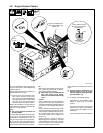
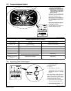
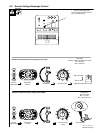
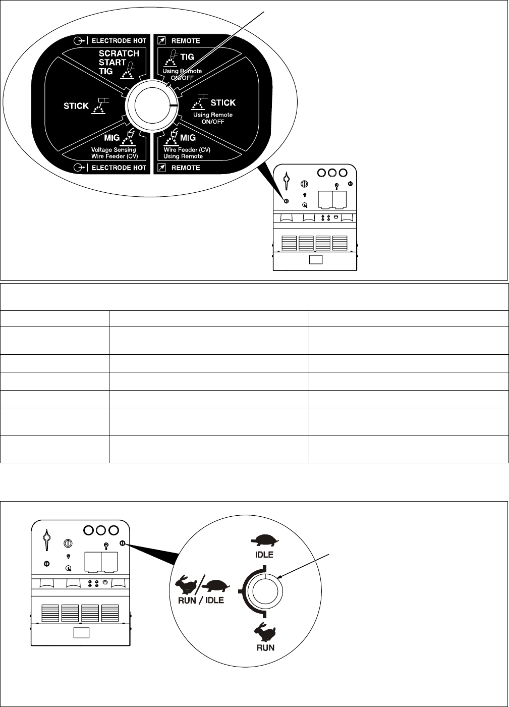
5-3. Process/Contactor Switch
1
1 Process/Contactor Switch
Y Weld output terminals are en-
ergized when Process/Con-
tactor switch is in any Elec-
trode Hot position and the en-
gine is running.
Use switch to select weld process
and weld output on/off control (see
table below and Section 5-5).
Place switch in Remote positions to
turn weld output on and off with a de-
vice connected to the remote 14 re-
ceptacle.
Place switch in Electrode Hot posi-
tions for weld output to be on whenev-
er the engine is running.
Use Stick position for air carbon arc
(CAC-A) cutting and gouging.
203 031-A-A / 802 580-A
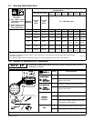
Process/Contactor Switch Settings
Switch Setting Process Output On/Off Control
Remote – TIG
GTAW With HF Unit, Pulsing Device,
Or Remote Control
At Remote 14 Receptacle
Remote – Stick Stick (SMAW) With Remote On/Off At Remote 14 Receptacle
Remote – MIG MIG (GMAW) At Remote 14 Receptacle
Electrode Hot – MIG MIG (GMAW) Electrode Hot
Electrode Hot – Stick
Stick (SMAW),
Air Carbon Arc (CAC-A) Cutting And Gouging
Electrode Hot
Electrode Hot – Scratch
Start TIG
Scratch Start TIG (GTAW) Electrode Hot
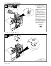
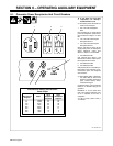
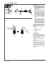
5-4. Operating Unit At Idle Speed
1
1 Engine Speed Switch
Use Idle speed when:
D Starting
D Stick welding at up to 180 A.
To weld above 180 A, place Engine
Speed switch in Run or Run/Idle
position.
When Stick welding at idle speed, the
front panel Voltage/Amperage control
setting is accurate up to 180 A. Above
180 A, weld output is slightly less than
Voltage/Amperage control setting.
. Place switch in Run or Run/Idle posi-
tion when using generator power.
. Place switch in Run position to oper-
ate most GMAW equipment.
203 031-A / 802 580-A