


OM-4401 Page 34
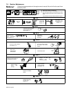
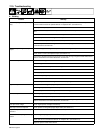
7-10. Troubleshooting
A. Welding
Trouble Remedy
No weld output; generator power output
okay.
Place Process/Contactor switch in a Electrode Hot position, or place switch in a Remote position and
connect remote contactor to optional Remote 14 receptacle RC1 (see Section 4-8).
Check position of polarity switch.
Reset circuit breaker(s) CB5 and CB6 (see Section 7-9). Check for faulty remote device connected to
RC1.
Check and secure connections to Remote 14 receptacle RC14 (see Section C).
Have Factory Authorized Service Agent check capacitor board PC4 and connections.
Check fuse F2, and replace if open (see Section 7-9).
Have Factory Authorized Service Agent check brushes and slip rings, field excitation circuit, field current
control board PC2, and the rotor.
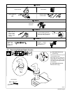
No weld output or generator power
output.
Disconnect equipment from generator power receptacles during start-up.
Check fuses F1 and F2, and replace if open (see Section 7-9).
Have Factory Authorized Service Agent check brushes and slip rings, integrated rectifier SR2, field ex-
citation circuit, field current control board PC2, and the rotor.
Erratic weld output. Check control settings.
Clean and tighten connections both inside and outside unit.
Be sure connection to work piece is clean and tight.
Remove excessive coils from weld cables.
Use dry, properly stored electrodes.
Check and adjust engine speed (see Section 7-8).
Check and secure lead connections to remote A/V control.
Have Factory Authorized Service Agent check brushes, slip rings, and field current control board PC2.
High weld output. Check position of Voltage/Amperage Adjust control.
Check engine speed, and adjust if necessary.
Have Factory Authorized Service Agent check field current regulator board PC2.
Low weld output. Check engine speed, and adjust if necessary.
Check fuse F2, and replace if open (see Section 7-9).
Have Factory Authorized Service Agent check brushes and slip rings, integrated rectifier SR2, field ex-
citation circuit, field current control board PC2, and the rotor.
Low open-circuit voltage. Check engine speed, and adjust if necessary.
Weld output cannot be adjusted. Check position of Voltage/Amperage Adjust switch (see Section 5-1).
No power output at Remote 14 recep-
tacle RC1.
Reset circuit breaker CB5 and/or CB6 (see Section 6-1).
No remote fine amperage or voltage
control.
Place Voltage/Amperage Adjust switch in Remote position.
Check and secure connections to Remote 14 receptacle RC1 (see Section 4-8).
Repair or replace remote control device.