


OM-4401 Page 18
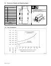
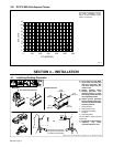
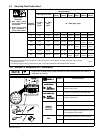
4-7. Selecting Weld Cable Sizes*
Weld Cable Size** and Total Cable (Copper) Length in Weld Circuit
Not Exceeding***
100 ft (30 m) or Less
150 ft
(45 m)
200 ft
(60 m)
250 ft
(70 m)
300 ft
(90 m)
350 ft
(105 m)
400 ft
(120 m)
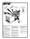
Weld Output
Terminals
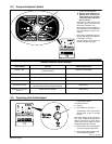
Y Stop engine before
connecting to weld out-
put terminals.
Y Do not use worn, dam-
aged, undersized, or
poorly spliced cables.
Welding
Amperes
10 – 60%
Duty
Cycle
60 – 100%
Duty
Cycle
10 – 100% Duty Cycle
100 4 (20) 4 (20) 4 (20) 3 (30) 2 (35) 1 (50) 1/0 (60) 1/0 (60)
150 3 (30) 3 (30) 2 (35) 1 (50) 1/0 (60) 2/0 (70) 3/0 (95) 3/0 (95)
200 3 (30) 2 (35) 1 (50) 1/0 (60) 2/0 (70) 3/0 (95) 4/0 (120) 4/0 (120)
250 2 (35) 1 (50) 1/0 (60) 2/0 (70) 3/0 (95) 4/0 (120)
2 ea. 2/0
(2x70)
2 ea. 2/0
(2x70)
300 1 (50) 1/0 (60) 2/0 (70) 3/0 (95) 4/0 (120)
2 ea. 2/0
(2x70)
2 ea. 3/0
(2x95)
2 ea. 3/0
(2x95)
350 1/0 (60) 2/0 (70) 3/0 (95) 4/0 (120)
2 ea. 2/0
(2x70)
2 ea. 3/0
(2x95)
2 ea. 3/0
(2x95)
2 ea. 4/0
(2x120)
400 1/0 (60) 2/0 (70) 3/0 (95) 4/0 (120)
2 ea. 2/0
(2x70)
2 ea. 3/0
(2x95)
2 ea. 4/0
(2x120)
2 ea. 4/0
(2x120)
* This chart is a guideline and may not suit all applications. If cable overheating occurs (normally you can smell it), use next size larger cable.
**Weld cable size (AWG) is based on either a 4 volts or less drop or a current density of at least 300 circular mils per ampere.
( ) = mm
2
for metric use S-0007-E–
***For distances longer than those shown in this guide, call a factory applications representative at 920-735-4505.
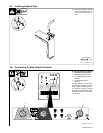
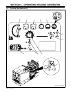
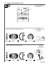
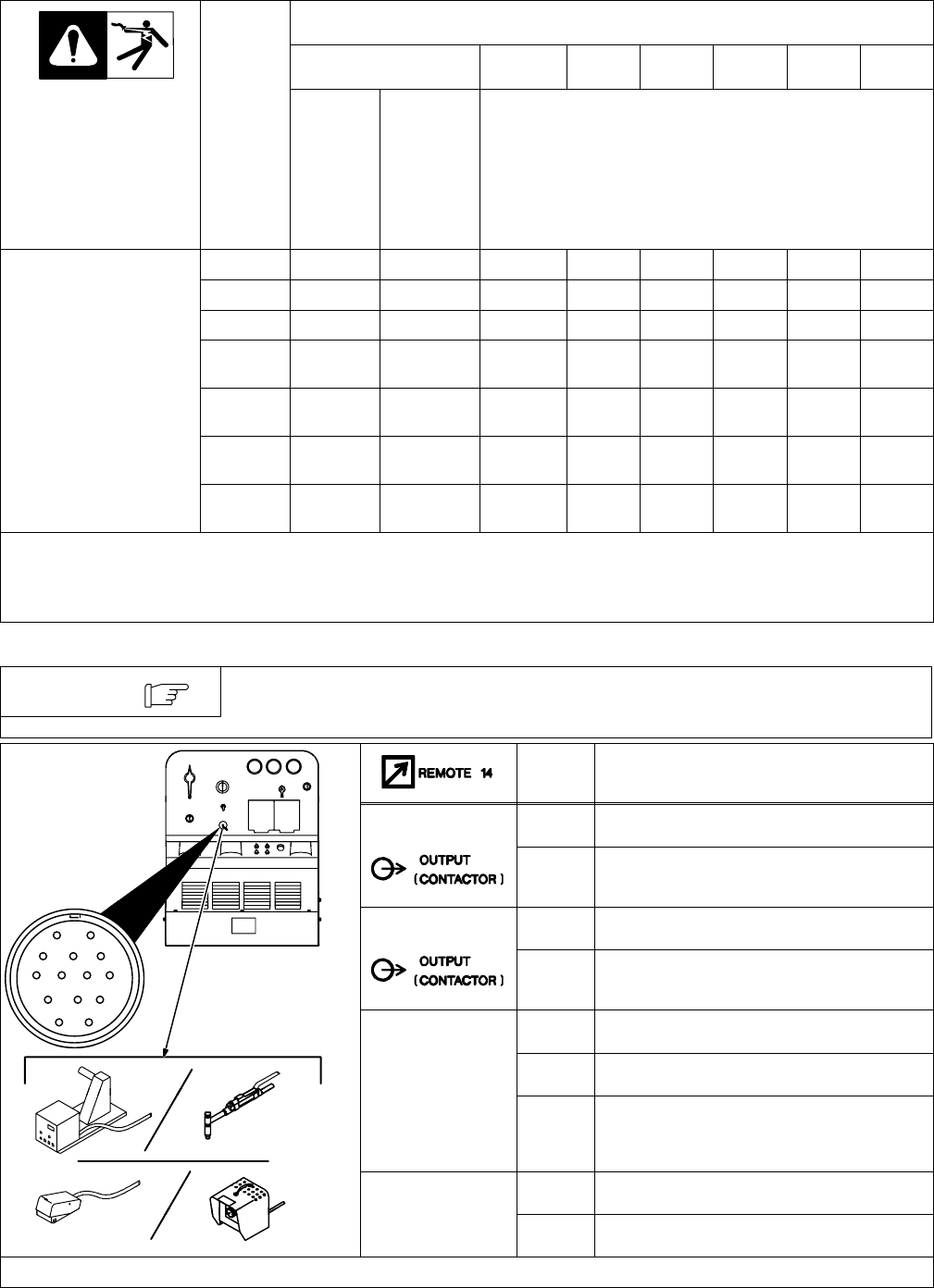
4-8. Remote 14 Receptacle RC1 Information
Engine runs at weld/power speed whenever a device connected to the remote 14
receptacle is running.
NOTE
Socket* Socket Information
24 VOLTS AC
A 24 volts ac. Protected by circuit breaker CB5.
24 VOLTS AC
B Contact closure to A completes 24 volts ac
contactor control circuit.
AJ
115 VOLTS AC
I 115 volts ac. Protected by circuit breaker CB6.
AJ
B
K
I
C
L
NH
M
115 VOLTS AC
J Contact closure to I completes 115 volts ac
contactor control circuit.
D
M
G
E
F
C Output to remote control; 0 to +10 volts dc.
REMOTE
D Remote control circuit common.
OUTPUT
CONTROL
E 0 to +10 volts dc input command signal from
remote control. Voltage is dependent on front pan-
el V/A Adjustment control setting.
G Circuit common for 24 and 115 volts ac circuits.
GND
K Chassis common.
*The remaining sockets are not used.