


MID-7604/7602 Power Drive 10 ni.com
If the DC power supplies are active, the green power LED illuminates.
If this LED fails to illuminate, check the power cord and the main input
fuse on the front panel.
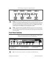
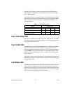
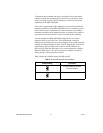
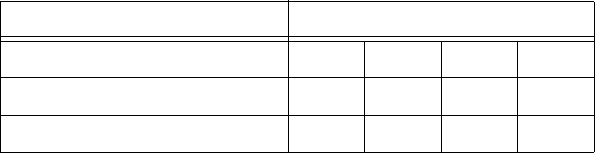
The LED status array is arranged by motor axes. Each of the four columns
represents an axis, and each of the three rows represents a particular status.
Table 1 summarizes the axis and status to which each LED in the 3 × 4
array corresponds.
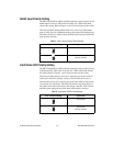
Driver Fault Output LEDs
The top row of LEDs indicates the status of the stepper drivers. An LED
illuminates red when an overcurrent condition or a problem with the motor
bus voltage on that axis occurs.
Driver Inhibit LEDs
The middle row of LEDs indicates whether or not a motor axis is inhibited.
An axis is inhibited and the LED illuminates yellow in the following
instances: if the host businterlock circuitry is activatedfrom the back panel,
if the ENABLE switch on the front panel is in the inhibit position, if the
motion controller’s inhibit signal is low, or if the per-axis inhibit input is
actively driven.
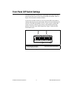
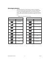
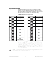
The polarity of the per-axis inhibit input is selectable from the front panel
DIP switches. Seethe FrontPanel DIP Switch Settings section of this guide
for more information.
Limit Status LEDs
The bottom rowof LEDs indicateswhether or nota limit switch is currently
active. The LED illuminates green if either the forward or reverse limit
switch is active for each axis. You can select the polarity for the limit status
LEDs from the front panel DIP switches. See the Front Panel DIP Switch
Settings section in this guide for more information.
Table 1. Front Panel LED Indicators
Status Motor Axis
Driver Fault Output (red) 1 2 3 4
Driver Inhibit (yellow) 1 2 3 4
Limit Status (green) 1 2 3 4