


MID-7604/7602 Power Drive 18 ni.com
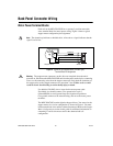
If the encoder cable length is greater than 10 ft, use encoders with line
driver outputs for your applications. Power for a +5 V encoder—generated
by a power supply inside the MID-7604/7602—is available on pin 7.
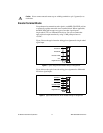
Note
If you require other encoder power voltages, reference an external power supply to
the Digital Ground signal on the 8-pin encoder terminal block.
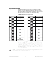
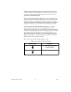
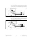
The MID-7604/7602 supports differential inputs for Phase A, Phase B, and
Index signals. You can easily accommodate encoders with various phase
relationships by swapping the signals and/or connecting them to the
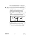
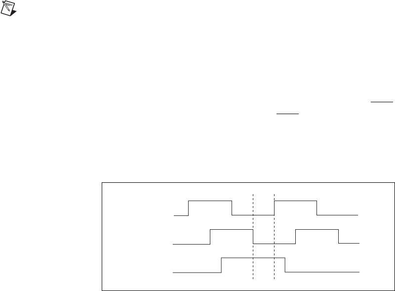
inverting inputs as specific applications require. The Index signal must
occur when both Phase A and Phase B signals are low, as shown in
Figure 7. If the Index polarity is inverted, try reversing the Index and Index
signals on differential encoders or using the Index input on single-ended
encoders.
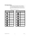
Figure 7 shows the proper encoder phasing for CW (forward) motor
rotation.
Figure 7. Encoder Signal Phasing, CW Rotation
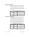
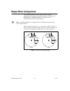
Closed-loop stepper applications require consistent directional polarity
between the motor and encoder for correct operation. The National
Instruments motion control standard directional polarity is as follows:
• Positive = forward = clockwise (CW) facing motor shaft
• Negative = reverse = counter-clockwise (CCW) facing motor shaft
Phase A
Phase B
Index