


© National Instruments Corporation 15 MID-7604/7602 Power Drive
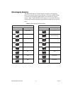
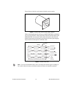
Inhibit Input Polarity Setting
The MID-7604/7602 has a DIP switch that globally sets the polarity for the
inhibit input for all axes. DIP switch 10 on the axis 1 DIP switch bank
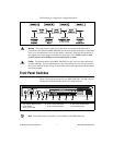
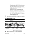
controls this setting. Refer to Figures 1 and 3 for the location of this switch.
The factory default setting of DIP switch 10 is active-low. If the inhibit
input is active, the axis is inhibited and the yellow status LED (middle row)
illuminates for the axis. Table 5 shows the DIP switch setting for the inhibit
input polarity selection.
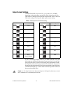
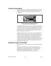
Limit Status LED Polarity Setting
The MID-7604/7602 has a DIP switch that globally sets the polarity for the
Limit Status LED. DIP switch 10 on the axis 2 DIP switch bank controls
this setting. Refer to Figures 1 and 3 for the location of this switch.
The factory default setting is active-low. Typically, you set the switch to
match your controller’s polarity setting, so that if either the reverse or
forward limits for an axis are active, the green status LED (on the bottom
row) for the axis illuminates. This DIP switch alters only the polarity for
the LEDs, and not the actual limit to the motion controller. Table 6 shows
the DIP switch setting for the Limit Status LED polarity selection.
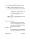
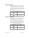
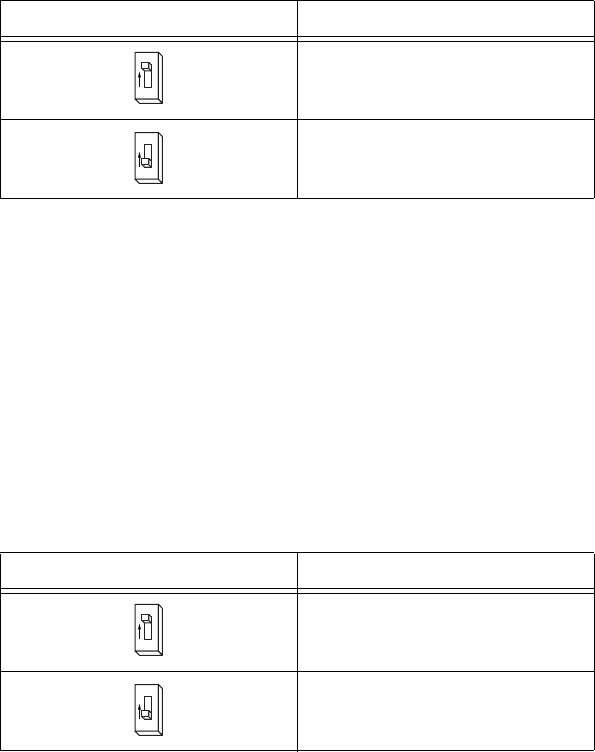
Table 5.
Inhibit Input Polarity DIP Switch Settings
Axis 1 Switch Setting Operation
Active-high
Active-low
(factory default)
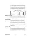
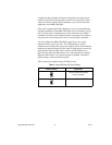
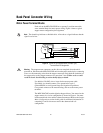
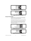
Table 6.
Limit Status LED DIP Switch Settings
Axis 2 Switch Setting Operation
Active-high
Active-low
(factory default)
10
O
N
10
O
N
10
O
N
10
O
N