


© National Instruments Corporation 7 MID-7604/7602 Power Drive
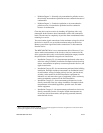
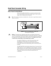
The following is a diagram of a sample installation.
Warning
The stepper motor connectors on this drive are energized when the unit is
powered on. Disconnect the MID-7604/7602 unit from the power outlet before connecting
wires to or disconnecting wires from the stepper connectors. Strip back the insulation of
the stepper wires to the stepper connectors no more than 7 mm. Failuretodosocould
result in electric shock leading to serious bodily injury or death.
Caution
The bottom surface of the MID-7604/7602 can get very hot to the touch under
certain conditions. To avoid a burn hazard, refer to the Output Current Settings section in
the Front Panel DIP Switch Settings section of this guide for the appropriate current setting
and safety hazards.
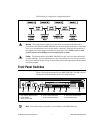
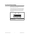
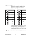
Front Panel Switches
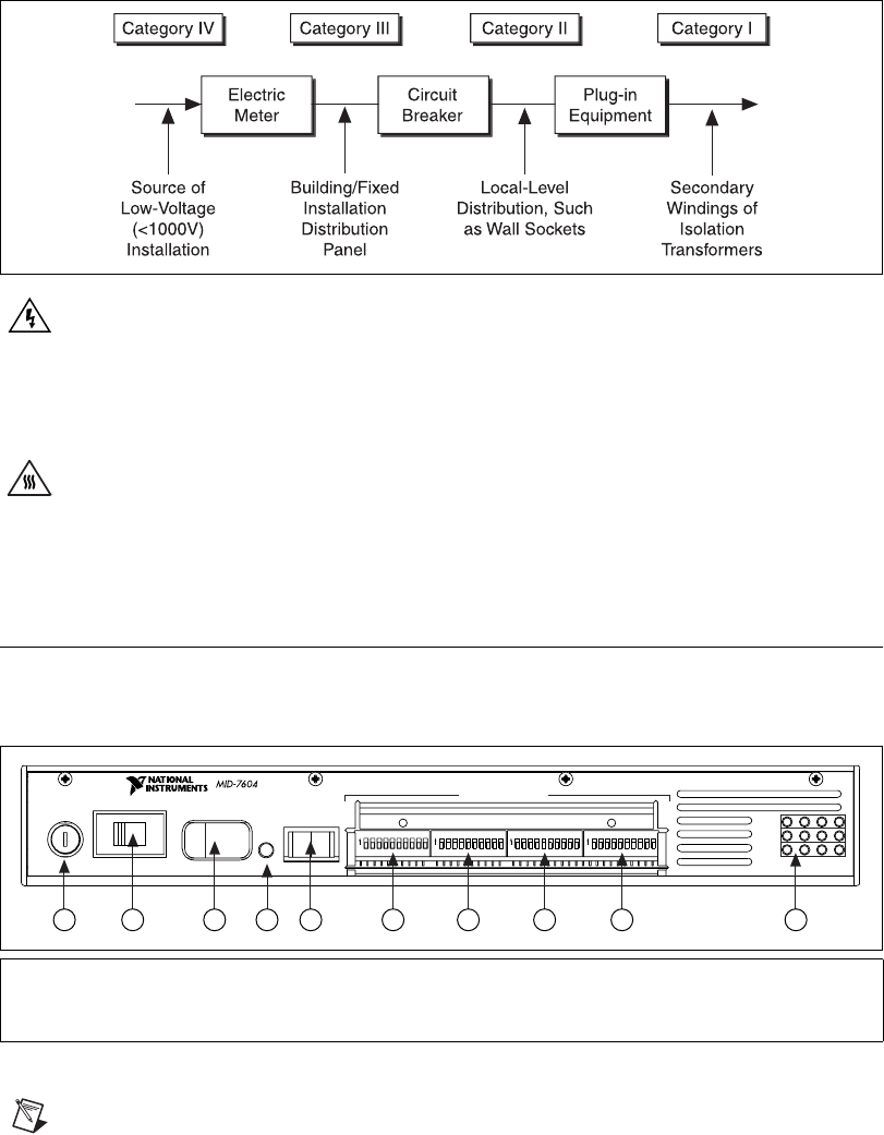
Figure 1 shows the front panel of your MID-7604/7602. The DIP switches
are shown with the detachable metal cover plate removed.
Figure 1. MID-7604/7602 Front Panel
Note
Items followed by an asterisk (*) are available on the MID-7604 only.
1 Main Input Fuse
2 Line Voltage Select Switch
3PowerSwitch
4GreenPowerLED
5 Enable Switch
6Axis1DIPSwitchBank
7Axis2DIPSwitchBank
8 Axis 3 DIP Switch Bank*
9 Axis 4 DIP Switch Bank*
10 LED Status Array
FUSE
LINE VOLTAGE SELECT
AC POWER
1
AXIS
234
ON OFF
+
5V
ON OFF
ENABLE
AXIS CONFIGURATION
1 2 3 4 105 6 7 8 9
ON ON ON ON
FAULTS
INHIBITS
LIMITS