


© National Instruments Corporation 11 MID-7604/7602 Power Drive
Front Panel DIP Switch Settings
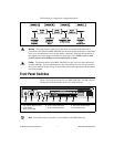
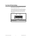
The MID-7604/7602 front panel has a detachable metal plate that when
removed provides access to four 10-position DIP switch banks. Refer to
Figure 1 for the location of these switches.
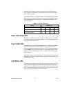
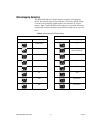
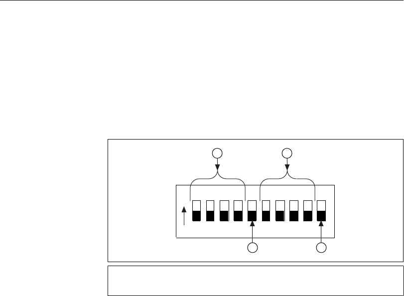
Use the first nine DIP switches on each 10-position DIP switch bank to
configure the microstep rate, peak output current, and current reduction for
each axis. The DIP switch banks for axes 1 and 2 contain a global DIP
switch, switch 10, which sets the polarity of the inhibit input and the
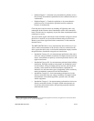
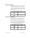
polarity of the limit status LED, respectively. Figure 3 shows the DIP
switch bank layout.
Figure 3.
DIP Switch Bank Layout
1 Peak Current Output Switches
2 Microstep Rate Switches
3 Current Reduction Switch
4 Global Polarity Switch (unused on
axes 3 and 4 DIP switch banks)
12345678910
O
N
1 2
3 4