


MID-7604/7602 Power Drive 16 ni.com
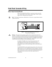
Back Panel Connector Wiring
Motor Power Terminal Blocks
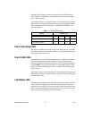
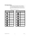
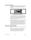
Each axis on the MID-7604/7602 has a separate 5-position removable
screw terminal block for motor power wiring. Figure 4 shows a typical
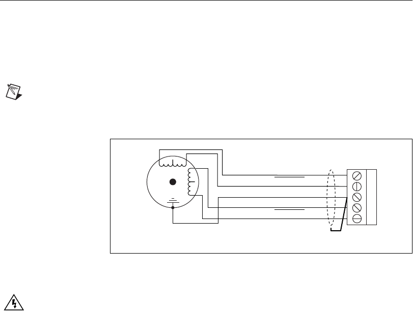
stepper motor configuration pin assignment.
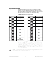
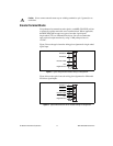
Note
The dotted loop indicates a shielded cable. A line above a signal indicates that the
signal is active-low.
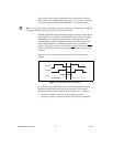
Figure 4. Typical Full-Coil Stepper Motor (2-Phase Type)
Terminal Block Pin Assignment
Warning
The stepper motor connectors on this drive are energized when the unit is
powered on. Disconnect the MID-7604/7602 unit from the power outlet before connecting
wires to or disconnecting wires from the stepper connectors. Strip back the insulation of
the stepper wires to the stepper connectors no more than 7 mm. Failuretodosocould
result in electric shock leading to serious bodily injury or death.
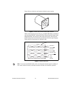
Use shielded, 20 AWG wire or larger for the motor power cable.
If available, you should connect a case ground wire to pin 3
(Ground/Shield) to avoid ground loops and signal noise problems.
Case ground connects to the motor housing, and not to the motor power
terminals.
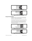
The MID-7604/7602 contains bipolar chopper drivers. You must wire the
stepper motors in a 4-wire configuration as shown in Figure 4. You must
isolate unused lead wires andleavethem disconnected. Referto the Stepper
Motor Configurations section in this guide for additional information on
connecting 6- and 8-wire motors and on the alternate half-coil
configuration.
1
2
3
4
5
Phase A
Phase B
Phase A
Case Ground
Shield
Stepper Motor
Phase B