


MID-7604/7602 Power Drive 8 ni.com
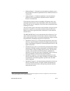
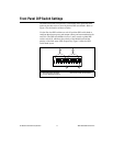
The two rocker switches on the MID-7604/7602 front panel are the
AC POWER and ENABLE. Figure 1 shows the location of these switches.
The AC POWER switch energizes the motor bus (+24 V) and the logic
(+5 V) power supplies. When switched on, the green power LED labeled
+5 V illuminates. If this LED fails to illuminate, check the power cord and
main input fuse on the front panel.
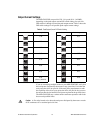
The ENABLE switch enables or inhibits the stepper drivers. If the
ENABLE switch is in the inhibit position (off), the stepper drivers are
inhibited, and the yellow LEDs (the middle row of the LED status array)
for all axes illuminate. See the Front Panel LEDs section of this guide for
more information.
Both the AC POWER and ENABLE switches can inhibit the stepper
drivers. However, as long as the AC POWER switch is on, only the stepper
driver output stages are disabled. The remaining circuitry remains active,
including the quadrature encoder circuit.
Caution
Yo u must change the MID-7604/7602 main input fuse on the front panel if you
change the line voltage from the factory setting. Refer to the Specifications section of this
guide for fuse specifications.
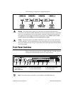
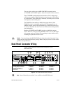
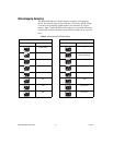
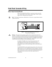
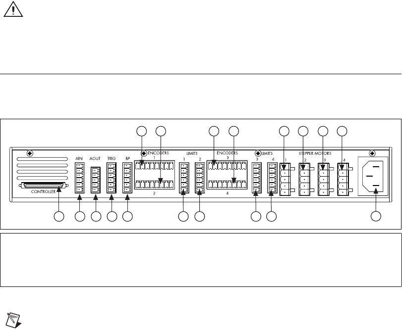
Back Panel Connector Wiring
Figure 2 shows connectors located on the back panel of your
MID-7604/7602.
Figure 2. MID-7604/7602 Back Panel Connectors
Note
Items followed by an asterisk (*) are available on the MID-7604 only.
1 Motion Controller Connector
2 Analog Input Connector
3 Analog Output Connector
4 Trigger Connector
5 Breakpoint Connector
6 AC Power
Encoder
Connectors
7Axis1
8Axis2
9Axis3*
10 Axis 4*
Limit
Connectors
11 Axis 1
12 Axis 2
13 Axis 3*
14 Axis 4*
Motor
Connectors
15 Axis 1
16 Axis 2
17 Axis 3*
18 Axis 4*
1 2 3 4 5
7
8
11 12
9
10
13 14
15
16
17
18
6