


© National Instruments Corporation 17 MID-7604/7602 Power Drive
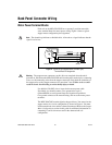
Caution
Never connect unused center taps or winding terminals to pin 3 (ground) or to
each other.
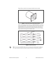
Encoder Terminal Blocks
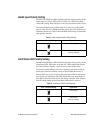
For quadrature incremental encoder signals, each MID-7604/7602 axis has
a separate 8-position removable screw terminal block. Where applicable,
the MID-7604/7602 accepts two types of encoder signal inputs:
single-ended (TTL) or differential line driver. You can accommodate
open-collector output encoders by using 2.2 kΩ pullup resistors to
+5 VDC.
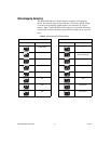
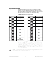
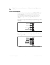
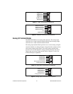
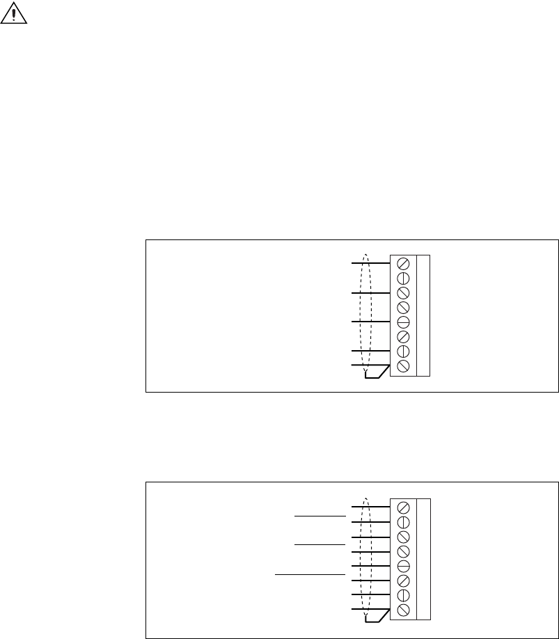
Figure 5 shows the typical encoder wiring pin assignment for single-ended
signal input.
Figure 5. Typical Single-Ended Encoder Wiring Pin Assignment
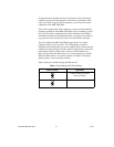
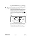
Figure 6 shows the typical encoder wiring pin assignment for differential
line driver signal inputs.
Figure 6.
Typical Differential Line Driver Encoder Wiring Pin Assignment
1
2
3
4
5
6
7
8
Encoder A
Encoder B
Encoder Index
+5 V
Digital Ground
1
2
3
4
5
6
7
8
Encoder A
Encoder A
Encoder B
Encoder B
Encoder Index
Encoder Index
+5 V
Digital Ground